DIN 48 SIZE DIGITAL TIMER
UL/C-UL , CE Approved
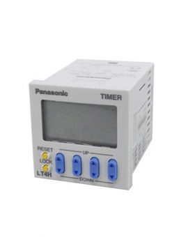
A brand new bright 2-color back light LCD display. The easy-to-read screen in any location makes checking and setting procedures a cinch.
Seesaw buttons make operating the unit even easier than before.
With a short body, it is easy to install in even narrow control panels.
The water-proof panel keeps out water and dirt for reliable operation even in poor environments.
Also offers a black panel cover to meet your design considerations.
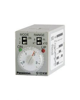
Set the operation mode and timer range with the DIP switches on the side of the unit.


Set the set time with the keys (UP/DOWN) on the front of the unit.
|
 |
Changing the set time
Power failure memory
The EEPROM is used for power failure memory. It has a life of Min. 105 over-writings.
The EEPROM is overwriting with the following timing.
| Output mode | Overwrite timing |
|---|---|
| Power ON delay (2) A2 | When power is OFF |
| Addition G | Change of preset value or start, reset input When power is OFF after being ON |
| Other modes | When power is OFF after changing preset value |
*Be aware that the contents of EEPROM for all models will be overwritten when power is turned OFF during input to external lock terminals (4) to (3) and [7] to [6]. Such an action does not exist by doing lock operation from the front.
| Operation type | Explanation | Time chart |
|---|---|---|
| Power on delay (1) (A) |
Set the operation mode section of the DIP switches (no.’s 1, 2, and 3) ・Clears elapsed time value and starts time delay at power ON. ・After timer completion, stops at the display of the set value (addition), or stops at “0” (subtraction). ・Ignores start input. ・Stops delay time operation at stop ON. ・Restarts delay time operation at stop OFF. |
 |
| Power on delay (2) (A2) |
Set the operation mode section of the DIP switches (no.’s 1, 2, and 3) ・Elapsed time value does not clear at power ON. (power outage countermeasure function) ・The output remains ON even after the power is cut and restarted. ・After timer completion, stops at the display of the set value (addition), or stops at “0” (subtraction). ・Ignores start input. ・Stops delay time operation at stop ON. ・Restarts delay time operation at stop OFF. |
 |
| Signal on delay (B) |
Set the operation mode section of the DIP switches (no.’s 1, 2, and 3) ・Clears elapsed time value at power ON. ・Time delay starts at start ON and elapsed time value or output resets at start OFF. ・Instantaneous time delay start at reset OFF and power ON while start is ON. ・Stops delay time operation at stop ON. Restarts delay time operation at stop OFF. ・In order to have the time delay start at power ON or reset at power OFF, short out the start input beforehand. |
 |
| Signal off delay (C) |
Set the operation mode section of the DIP switches (no.’s 1, 2, and 3) ・Clears elapsed time value at power ON. ・Output control ON at start ON and time delay start at start OFF. ・Elapsed time value clears when start goes ON again during time delay. ・Stops delay time operation at stop ON. ・Restarts delay time operation at stop OFF. |
 |
| Operation type | Explanation | Time chart |
|---|---|---|
| Pulse One-shot (D) |
Set the operation mode section of the DIP switches (no.’s 1, 2, and 3) ・Clears elapsed time value at power ON. ・Time delay starts and output control ON at start ON. ・Turns output control OFF and clears elapsed time value at time-up. ・Ignores start input during time delay. ・Stops delay time operation at stop ON. ・Restarts delay time operation at stop OFF. In order to have the time delay start at power ON or reset at power OFF, short out the start input beforehand. |
 |
| Pulse On delay (E) |
Set the operation mode section of the DIP switches (no.’s 1, 2, and 3) ・Clears elapsed time value at power ON. ・Time delay starts at start ON. ・Ignores start input during time delay. ・Stops delay time operation at stop ON. ・Restarts delay time operation at stop OFF. In order to have the time delay start at power ON or reset at power OFF, short out the start input beforehand. |
 |
| Signal Flicker (F) |
Set the operation mode section of the DIP switches (no.’s 1, 2, and 3) ・Clears elapsed time value at power ON. ・Time delay starts at start ON. ・Ignores start input during time delay. ・Output control reverses, elapsed time value clears, and timer delay starts at timer completion. ・Stops delay time operation at stop ON. ・Restarts delay time operation at stop OFF. In order to have the time delay start at power ON or reset at power OFF, short out the start input beforehand. |
 |
| Totalizing On delay (G) |
Set the operation mode section of the DIP switches (no.’s 1, 2, and 3) ・Elapsed time value does not clear at power ON. (power outage countermeasure function) ・The output remains ON even after the power is off and restarted. ・Stops delay time operation at stop ON. ・Restarts delay time operation at stop OFF. |
 |
| Type | Ralay output type | Transistor output type | ||||
|---|---|---|---|---|---|---|
| Item | AC type AC/DC type | DC type | AC type AC/DC type | DC type | ||
| Rating | Rated operating voltage | 100 to 240 V AC, 24 V AC, 24 V AC/DC | 12 to 24 V DC | 100 to 240 V AC, 24 V AC, 24 V AC/DC | 12 to 24 V DC | |
| Rated frequency | 50/60 Hz common | – | 50/60 Hz common | – | ||
| Rated power consumption | Max. 10 V A | Max. 3 W | Max. 10 V A | Max. 3 W | ||
| Rated control capacity | 5 A, 250 V AC (resistive load) | 100 mA, 30 V DC | ||||
| Time range | 9.999 s, 99.99 s, 999.9 s, 9999 s, 99 min 59 s, 999.9 min, 99 h 59 min, 999.9 h (selected by DIP switch) | |||||
| Time counting direction | Addition (UP)/Subtraction (DOWN) (2 directions selectable by DIP switch) |
|||||
| Operation mode | A (Power ON delay 1), A2 (Power ON delay 2), B (Signal ON delay), C (Signal OFF delay), D (Pulse one-shot), E (Pulse ON delay), F (Signal Flicker), G (Totalizing ON delay) (selectable by DIP switch) | |||||
| Start/Reset/Stop input | Min. input signal width: 1 ms, 20 ms (2 directions by selected by DIP switch) (The 8-pin type does not have a stop input.) | |||||
| Lock input | Min. input signal width: 20 ms (The 8-pin type does not have a lock input.) | |||||
| Input signal | Open collector input Input impedance: Max. 1 kΩ; Residual voltage: Max. 2 V Open impedance: 100kΩ or less, Max. energized voltage: 40V DC |
|||||
| Indication | 7-segment LCD (LT4H, LT4H-L common), Elapsed value (backlight red LED), Setting value (backlight yellow LED) | |||||
| Power failure memory method | EEP-ROM (Min. 105 overwriting) | |||||
| Time accuracy (max.) | Operating time fluctuation | ± (0.005 % + 50 ms) in case of power on start ± (0.005 % + 20 ms) in case of input signal start [Operating voltage: 85 to 110% Temperature: -10 to +55°C/ +14 to +131°F Min. input signal width: 1ms] |
||||
| Temperature error | ||||||
| Voltage error | ||||||
| Setting error | ||||||
| Contact | Contact arrangement | Timed-out 1 Form C | Timed-out 1 Form A (Open collector) | |||
| Contact resistance (Initial value) | 100 mΩ (at 1 A 6 V DC) | – | ||||
| Contact material | Ag alloy/Au flash | – | ||||
| Life | Mechanical (contact) | Min. 2 × 10⁷ ope. (Except for switch operation parts) | – | |||
| Electrical (contact) | 1.0 × 10⁵ ope. (At rated control voltage) | Min. 107 ope. (At rated control voltage) | ||||
| Electrical | Allowable operating voltage range | 85 to 110 % of rated operating voltage | ||||
| Breakdown voltage (Initial value) |
2,000 Vrms for 1 min: Between live and dead metal parts (11-pin) 2,000 Vrms for 1 min: Between input and output 1,000 Vrms for 1 min: Between contacts |
2,000 Vrms for 1 min: Between live and dead metal parts (Pin type) 2,000 Vrms for 1 min: Between input and output |
||||
| Insulation resistance (Initial value) |
Min. 100 MΩ: Between live and dead metal parts Between input and output Between contacts (At 500V DC) |
Min. 100 MΩ: Between live and dead metal parts Between input and output (At 500V DC) |
||||
| Operating voltage reset time | Max. 0.5 s | |||||
| Temperature rise | Max. 65° C (under the flow of nominal operating current at nominal voltage) | – | ||||
| Mechanical | Vibration resistance | Functional | 10 to 55 Hz: 1 cycle/min single amplitude of 0.35 mm .014 inch (10 min on 3 axes) | |||
| Destructive | 10 to 55 Hz: 1 cycle/min single amplitude of 0.75 mm .030 inch (1 h on 3 axes) | |||||
| Shock resistance | Functional | Min. 98 m 321.522 ft./s2 (4 times on 3 axes) | ||||
| Destructive | Min. 294 m 964.567 ft./s2 (5 times on 3 axes) | |||||
| Operating conditions | Ambient temperature | -10°C to 55°C/ +14°F to +131°F | ||||
| Ambient humidity | Max. 85 % RH (non-condensing) | |||||
| Air pressure | 860 to 1,060 h Pa | |||||
| Ripple rate | – | 20 % or less | – | 20 % or less | ||
| Connection | 8-pin/11-pin/screw terminal | |||||
| Protective construction | IP66 (front panel with rubber gasket) | |||||