 |
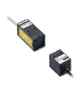
The sensor head can be changed safely without turning off the controller. This reduces the man-hours required for changing the line setup when different workpieces need to be processed. |
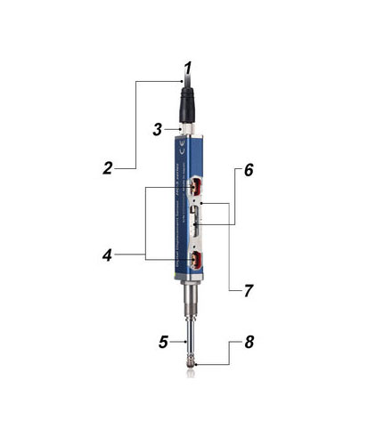
The two plain bearings are accurately aligned with the center of the spindle during their installation to the top and bottom sections of the body to ensure smooth sliding.
 |
The two plain bearings are accurately aligned with the center of the spindle during their installation to the top and bottom sections of the body to ensure smooth sliding. The sensor can withstand more than 100 million sliding operations under application of lateral load (reference value).
* F = Force |
 |
Even when a sudden upward thrust impact occurs, the resulting load is applied only to the lower section of the sensor unit because a spindle stopper minimizes the impact on the glass scales. |
 |
|
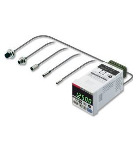
Useful maintenance mode for the production floor.
The following data are stored and can be used for analysis on the spot:
An alarm can be set to notify the user of an upward thrust (stroke) that exceeds the set level. This allows you to conduct a preventive maintenance before the sensor head generates a malfunction.
 |
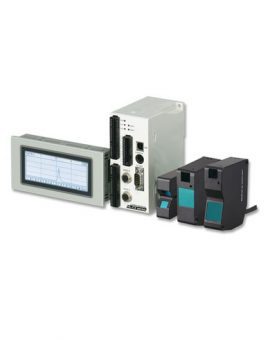
The 2-line digital display simultaneously shows head measurement (measured value) and judgment value (calculated value). The high-contrast LCD provides sharp and clear indications and offers a wide viewing angle.
|
 |
Values within the maximum and minimum limits are indicated in green. Values outside the valid range are indicated in orange. This allows users to check the margin to the limits at a glance.
|
 |
During configuration of the master unit, the copy function symbol lights up for setting items that can be copied to slave units. This significantly reduces the man-hours required for configuration and maintenance. |
 |
Align with master workpiece and press ENTER for easy tolerance setting.
1. Master workpiece 4. Tolerance on positive side (HIGH set value) |
 |
The measurement process does not need to be triggered externally. It starts automatically when either the fluctuation of measurement values has stabilized or with a specified time delay after the self-trigger level (ST level) has been reached
1. Static width setting 2. Delay timer setting ❶ High |
 |
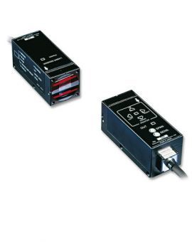
One master unit can be connected in series with up to 15 slave units in any order. This allows easy multi-point calculations. End plates (optional) must be mounted on both sides of the controller after the connection of slave units.
Unit types Master unit (1 type): High performance type (analog current + input / output) Slave unit (3 types ):
1. End plates MS-DIN-E |
 |
 |
 |
| Coupling assembly inspection | Installed height measurement | Crankshaft measurement |
 |
 |
 |
| Screw head height measurement | Transmission parts height measurement | Management of press-fit points of press-fit parts |
 |
 |
 |
| Motor shaft eccentricity measurement | Flat screen flatness measurement | Resin roller eccentricity measurement |
| Type | Resolution | Indication accuracy (P-P, full range) | Measurement range | Model No. | |
|---|---|---|---|---|---|
| General purpose | Standard type | 0.5μm | Max. 2.0μm | 10mm | HG-S1010 |
| Low measuring force type (note 1) | HG-S1010R | ||||
| High precision | Standard type | 0.1μm | Max. 1.0μm | HG-S1110 | |
| Low measuring force type (note 1) | HG-S1110R | ||||
Note 1: The low measuring force type is not equipped with rubber bellows.
Sensor head connection cable (bending-resistant type)
| Designation | Length | Model No. |
|---|---|---|
| Straight connector | 3m | CN-HS-C3 |
| 7m | CN-HS-C7 | |
| 20m | CN-HS-C20 | |
| L-shaped connector | 3m | CN-HS-C3L |
| 7m | CN-HS-C7L | |
| 20m | CN-HS-C20L |
| Type | Output | Model No. | |
|---|---|---|---|
| Master unit | High-performance type (analog current + input / output) | NPN | HG-SC101 |
| PNP | HG-SC101-P | ||
| Slave units | High-performance type (analog current + input / output) | NPN | HG-SC111 |
| PNP | HG-SC111-P | ||
| Standard type (input / output) | NPN | HG-SC112 | |
| PNP | HG-SC112-P | ||
| Wire-saving type | – | HG-SC113 | |
| Designation | Model No. | |
|---|---|---|
| Probe | Standard type | TR-S10-Cx5 (5 pcs. per set) |
| Super-hard type | TR-S10-H | |
| Super-hard needle type | TR-S321-H | |
| Flat-seated type | TR-S411-K | |
| Roller type | TR-S601 | |
| Offset type | TR-S700-H | |
| Joint | Length 15mm type | TR-J102 |
| Length 25 mm type | TR-J104 | |
| Rubber bellows | TR-G20x5 (5 pcs. per set]) | |
 |
 |
 |
| TR-S10-Cx5 (5 pcs. per set) Standard type |
TR-S10-H Super-hard type |
TR-S321-H Super-hard needle type |
 |
 |
 |
| TR-S411-K Flat-seated type |
TR-S601 Roller type |
TR-S700-H Offset type |
 |
 |
| TR-J102 Length 15mm type |
TR-J104 Length 25 mm type |
 |
| TR-G20x5 (5 pcs. per set) |
| Type | General purpose | High precision | |||
|---|---|---|---|---|---|
| Standard type | Low measuring force type | Standard type | Low measuring force type | ||
| Model No. | HG-S1010 | HG-S1010R | HG-S1110 | HG-S1110R | |
| Compatible controller | HG-SC101(-P), HG-SC111(-P), HG-SC112(-P), HG-SC113 | ||||
| Position detection method | Optical absolute linear encoder method | ||||
| Measurement range | 10mm (note 1) | ||||
| Stroke | Min. 10.5mm (note 1) | ||||
| Measuring force (note 2, note 3) | Downward mount | Max. 1.65N 1.1N (note 4) |
Max. 0.35N 0.3N (note 4) |
Max. 1.65N 1.1N (note 4) |
Max. 0.35N 0.3N (note 4) |
| Upward mount | Max. 1.35N 0.85N (note 4) |
Max. 0.12N 0.05N (note 4) |
Max. 1.35N 0.85N (note 4) |
Max. 0.12N 0.05N (note 4) |
|
| Side mount | Max. 1.5 N 0.95N (note 4) |
Max. 0.25N 0.2N (note 4) |
Max. 1.5N 0.95N (note 4) |
Max. 0.25N 0.2N (note 4) |
|
| Resolution | 0.5μm | 0.1μm | |||
| Indication accuracy (P-P) (note 2) |
Full range: max. 2.0μm Narrow range: max. 1.0μm (any 60μm) |
Full range: max. 1.0μm Narrow range: max. 0.5μm (any 60μm) |
|||
| Tip deviation amount | 35μm (typical) | ||||
| Hot-swap function | Incorporated | ||||
| Operation indicator | 2-color LED (orange / green) | ||||
| Environmental resistance |
Protective structure | IP67 (IEC, note 5) | – | IP67 (IEC, note 5) | – |
| Ambient temperature | Operation: -10 to +55°C (no condensation or ice) Storage: -20 to +60°C |
||||
| Ambient humidity | 35 to 85% RH, storage: 35 to 85% RH | ||||
| Insulation resistance | Min. 100MΩ at 250V DC | ||||
| Vibration resistance | 10 to 500Hz frequency, 3mm double amplitude (maximum acceleration 196m/s²) in X, Y and Z directions for two hours each | ||||
| Shock resistance | 1960m/s² acceleration in X, Y and Z directions three times each | ||||
| Mechanical life | Min. 100 million times (note 6) | ||||
| Tightening torque | Set screw: 1.5N m, nut: 12.5N m | ||||
| Probe tightening torque | 0.1 to 0.4N m (no force applied to main unit) | ||||
| Grounding method | Capacitor grounding | ||||
| Material | Body: zinc, holder: stainless steel, spindle: tool steel, probe (note 7): ceramic, rubber bellows: NBR (black) | ||||
| Weight | Net weight: approx.. 80g | ||||
| Accessories | Standard type (HG-S1010 / HG-S1110): Sensor head fastening wrench 1 pc., mounting nut 1 pc. Low measuring force type (HG-S1010R / HG-S1110R): Sensor head fastening wrench 1 pc., mounting nut 1 pc., rubber bellows 1 pc. |
||||
Notes:
1. 5 to 10mm range when low measurement force type (HG-S1010R / HG-S1110R) is mounted in upward mount.
2. Measured at an ambient temperature of +20°C
3. In the case of low measuring force type (HG-S1010R / HG-S1110R), measurements were obtained with products in standard configuration without rubber bellows.
4. Typical value near center of measurement.
5. Excludes damage and deterioration to rubber bellows due to external causes.
6. Typical value in a clean environment with no contact with dust or liquids such as water and oil. Four million times (typical) when low measurement force type (HG-S1010R / HG-S1110R) is mounted in upward mount.
7. Different probes (optional) are also available.
| Type | Master unit | Slave unit | |||
|---|---|---|---|---|---|
| High-performance type | High-performance type | Standard type | Wire-saving type | ||
| Model No. | NPN output | HG-SC101 | HG-SC111 | HG-SC112 | HG-SC113 |
| PNP output | HG-SC101-P | HG-SC111-P | HG-SC112-P | ||
| Compatible sensor head | HG-S1010(R), HG-S1110(R) | ||||
| Number of connectable units | Up to 15 slave units can be connected per master unit. | ||||
| Supply voltage | 24V DC ±10%, including ripple 0.5V (P-P) | ||||
| Current consumption (note 2) | Max. 70mA (when sensor head is connected) | ||||
| Analog current output (note 3) |
|
– | |||
| Control output (output 1, output 2, output 3) |
NPN output type
PNP output type
|
– | |||
| Short-circuit protection | Incorporated (automatic reset type) | – | |||
| Judgment output | NO / NC switching method | – | |||
| Alarm output | Open when alarm occurs | – | |||
| External input (input 1, input 2, input 3) |
NPN output type
PNP output type
|
– | |||
| Trigger input | Input time min. 2ms (ON) | – | |||
| Preset input | Input time min. 20ms (ON) | – | |||
| Reset input | Input time min. 20ms (ON) | – | |||
| Bank input A / B | Input time min 20ms (ON) | – | |||
| Response time | 3ms, 5ms, 10ms, 100ms, 500ms, 1,000ms switching type | ||||
| Digital display | 204-segment LCD | ||||
| Display resolution | 0.1μm | ||||
| Display range | -199.9999 to 199.9999mm | ||||
| Contamination level | 2 | ||||
| Altitude | Max. 2000m | ||||
| Environmental resistance |
Degree of protection | IP40 (IEC) | |||
| Ambient temperature | -10 to +50°C (no condensation or ice), storage: -20 to +60°C | ||||
| Ambient humidity | 35 to 85% RH, storage: 35 to 85% RH | ||||
| Insulation resistance | Min. 20MΩ, with 250V DC megger between all supply terminals connected together and enclosure | ||||
| Withstand voltage | 1000V AC for one minute between all supply terminals connected together and enclosure | ||||
| Vibration resistance | 10 to 150Hz frequency, 0.75mm amplitude in X, Y and Z directions for two hours each | ||||
| Shock resistance | 98m/s² acceleration (10G approx.) in X, Y and Z directions five times each | ||||
| Material | Case: polycarbonate, cover: polycarbonate, switches: polyacetal | ||||
| Cable | 0.2mm² 2-core cable (brown and blue lead wires) / 0.15mm² 7-core composite cable, 2m long | 0.15mm², 7-core composite cable, 2m long | 0.15mm², 6-core cab tire cable, 2m long | – | |
| Weight (approx.) | 140g | 140g | 130g | 60g | |
Notes:
1. Where measurement conditions have not been specified precisely, the conditions used were as follows: supply voltage 24V DC, ambient temperature +20°C.
2. Current consumption does not include analog current output.
3. Linearity F.S. = 16 mA, and is linearity with respect to digitally measured values.
4. When slave units are connected to the master unit, the maximum sink current / source current of the control output and ambient temperature vary depending on the number of connected slave units as shown below.
| Number of connected slave units | Maximum sink current / source current of control output | Ambient temperature |
|---|---|---|
| 1 to 7 slave units | 20mA | -10 to +45°C |
| 8 to 15 slave units | 10mA |