Seven Steps to Higher Efficiency
All about efficiencies for your manufacturing
UL/C-UL , CE Approved
CE : EMC Directive(Excluding AFPRP2□)
UL : Excluding some models


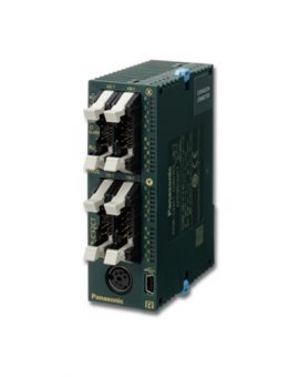
Models with built-in Ethernet ports add functionality to CPU unit.
Easy connection with all kinds of robots and PLCs enables control and communication.
* EtherNet/IP is a trademark of ODVA, Inc.

With ease and at low cost, extend the serial communication and analog functionality of CPU units.

Moreover, when used as a serial communication unit, expansion to as many as 35 channels is possible. Reduces cost and footprint.


To enable information collection, because the FP7 can deal with any protocol for Ethernet / serial communications, the FP7 can be installed in existing facilities.

Communicate easily with many units, including automation control equipment such as PLCs and information equipment such as PCs.


Logging set up is done via the configuration screen. Moreover, it is possible to keep up to 16 files concurrently active.
・Various triggers: periodic, cycle, bit, startup, etc

Diagnosis of rewrite life of SD memory card helps protect valuable information assets

* Diagnosis possible when Panasonic industrial-spec SD memory cards are used.

Reference value: for 196 k steps type CPU unit (Note)
| Program | 234k steps |
221k steps |
196k steps |
145k steps |
52k steps |
|---|---|---|---|---|---|
| Data register |
64k words |
128k words |
256k words |
512k words |
976k words |
Note:For data register (DT), data up to 256 k words can be backed up.

Allows the PC to read the logging data in the FP7’s SD memory card and to write setting values and other parameters.

The FP7 can generate and write data files to an FTP server on a PC as well as read data files from the FTP server.
The sessions use SSL, protecting IDs and passwords.

Transfer data from the FP7 to a web server for easy viewing with a browser. Send and receive data from multiple FP7 units on a schedule controlled by the FP7.
Communicate both inside the firewall on an intranet and outside the firewall to the wider world through the Internet.

Allow users from around the world to access the current state of their equipment.


Monitor and control the FP7 without the use of custom software. Users can check the accumulated data in the FP7 with a browser.

Custom Web
Screens (content) that are setup as desired by the user with Control Web Creator are uploaded to the FP7. Then, the information in the FP7’s internal Web server can be monitored on a browser.

* Ethernet is a registered trademark of Fuji Xerox Co., Ltd. and Xerox Corporation.
Control Web Creator
This is a graphics creation tool that allows you to easily design Web content that is published by the FP7. You can creatively design content by arranging Web components such as switches, lamps and meters on the screen and then setting the properties. Your content will be linked to information in the PLC without needing any knowledge of HTML.
・Same style of operation as the program display image creation tool
・Components can be arranged by dragging and dropping.
・Detailed component settings are easy using properties.
・Components don’t lose quality when enlarged or reduced, and you can color them as desired.
・Images can be pasted in.

This is the Web content that is contained as default in the CPU unit.
Status of the FP7 (settings, operation history, errors, etc.) can be checked.

Even without Control FPWIN GR7 ladder editing software, as long as you have a browser, you can check the FP7 status.
You can view the data register, etc., using a PC or smartphone.
The managers can receive and view e-mailed malfunction notifications and daily reports of equipment operations.
E-mail sending function (SSL-compatible)
Use instructions and timings controlled by the FP7 to send e-mails on a pre-set schedule or when a pre-set condition changes in the PLC. The e-mails can have data files attached and communication is SSL-capable to protect the e-mails.

A
| Item | AFP7CPS41E(S) (Note 6) | |||||
|---|---|---|---|---|---|---|
| Memory capacity |
Memory selection pattern (Note 1) |
1 | 2 | 3(Factory default) | 4 | 5 |
| Program (steps) (Note 2) | 234,000 | 221,500 | 196,000 | 144,500 | 51,500 | |
| Data register (words) (Note 2) |
65,536 | 131,072 | 262,144 | 524,288 | 999,424 | |
| Number of max. program block (PB) |
468 | 443 | 392 | 289 | 103 | |
| Item | AFP7CPS31E(S)/AFP7CPS31(S) (Note 6) | ||||
|---|---|---|---|---|---|
| Memory capacity |
Memory selection pattern (Note 1) |
1(Factory default) | 2 | 3 | 4 |
| Program (steps) (Note 2) | 121,500 | 96,000 | 64,000 | 32,000 | |
| Data register (words) (Note 2) |
131,072 | 262,144 | 425,984 | 589,824 | |
| Number of max. program block (PB) |
243 | 192 | 128 | 64 | |
| Item | AFP7CPS21 | ||
|---|---|---|---|
| Memory capacity |
Memory selection pattern (Note 1) |
1(Factory default) | 2 |
| Program (steps) (Note 2) | 64,000 | 32,000 | |
| Data register (words) (Note 2) |
131,072 | 262,144 | |
| Number of max. program block (PB) |
128 | 64 | |
| Item | AFP7CPS41E(S) / AFP7CPS31E(S) / AFP7CPS31(S) / AFP7CPS21 |
|---|---|
| Programming method | Relay symbol method |
| Control method | Cyclic operation method |
| Program memory | Built-in flash ROM (no backup battery required) |
| Operation speed | Basic instruction: Min. 11 ns/step (AFP7CPS21: 14 ns/step) |
| External input (X) / output (Y) | 8,192 points (Note 4) / 8,192 points (Note 4) |
| Internal relays (R) | 32,768 points |
| System relays (SR) | Indicate operation status of various relays is shown. |
| Link relays (L) | 16,384 points |
| Timers (T) | 4,096 points: Timer capable of counting (units: 10 μs, 1 ms, 10 ms, 100 ms or 1 sec.) × 4,294,967,295 |
| Counters (C) | 1,024 points, Counter capable of counting 1 to 4,294,967,295 |
| Link data registers (LD) | 16,384 words |
| System data registers (SD) | Internal operation status of various registers is shown. |
| Index registers (I0 to IE) | 15 long words / With switching function |
| Master control relay (MCR) | Unlimited |
| Number of labels (LOOP) | Max. 65,535 points for each program block (PB) |
| Differential points | Unlimited |
| Number of step ladders | Unlimited |
| Number of subroutines | Max. 65,535 points for each program block (PB) |
| Number of interrupt programs | 1 periodical interrupt program |
| SD memory card function | SDHC memory cards of up to 32 GB are usable. *except for AFP7CPS21 |
| Constant scan | Available (0 to 125 ms) |
| Real time clock (Note 3) |
Built in. Date backup with battery. |
| Battery life | 3.3 years or more (at 25 ℃ 77 ℉) (when no power is supplied) *except for AFP7CPS21 |
| Security function (Note 5) |
Password / Restricted distribution / Read disable setting / Encryption |
| PLC link function | Max. 16 units, link relays: 1,024 points, link registers: 128 words. (Data transfer and remote programming are not supported) (Link area allocation is switchable between the first and the second half) |
Notes :
1)The factory default setting is pattern 3 for AFP7CPS41E(S) and pattern 1 for AFP7CPS31E(S), AFP7CPS31(S) and AFP7CPS21.
2)For data register (DT), data up to 262,144 words can be backed up.
3)Precision of calendar; At 0 ℃ 32 ℉, less than 95 seconds error per month, At 25 ℃ 77 ℉, less than 15 seconds error per month, At 55 ℃ 131 ℉, less than 130 seconds error per month
4)Hardware configuration governs the actually usable number of I/O points. When I/O points are not actually used, usable as internal relays.
5)Encryption can be used for AFP7CPS41ES, AFP7CPS31ES and AFP7CPS31S.
6)Products with an “S” at the end of a part number have the encryption function.
| Item | Specifications |
|---|---|
| Interface | RS232C, three-wire system, 1 channel (Note 1) |
| Transmission distance | 15 m 49 ft |
| Transmission speed | 300, 600, 1200, 2400, 4800, 9600, 19200, 38400, 57600, 115200, 230400 bits/sec, |
| Communication method | Half-duplex system |
| Synchronous method | Start-stop synchronization system |
| Transmission format | Stop bit: 1 bit / 2 bits |
| Parity: none / odd / even | |
| Data length: 7 bits / 8 bits | |
| Start code: with STX / without STX | |
| End code: CR / CR + LF / none / ETX | |
| Data transmission order | Transmit from bit 0 in character units. |
| Communication mode | General-purpose communication, Computer link and MODBUS-RTU |
Note: 1) SD, RD and SG terminals are isolated from internal circuits.
| Terminal (Note 1) | Connecting Programmable Display model |
|---|---|
| 5 V | For 5 V DC type GT series Programmable Display |
| 24 V (Note 2) | For 24 V DC type GT series Programmable Display |
Notes:
1) 5 V and 24 V DC types are not usable at the same time.
2) Use 21.6 to 26.4 V DC to power the CPU unit. Please check the “GT Series Hardware Manual” for grounding of the GT series programmable display. The AFP7CPS21 is not provided with this port.
| Item | Specifications |
|---|---|
| Communication interface | Ethernet 100BASE-TX / 10BASE-T |
| Baud rate | 100 Mbps, 10 Mbps auto negotiation function |
| Total cable length | 100 m 328 ft (500 m 1,640 ft when a repeater is used) |
| Number of nodes | Max. 254 units |
| Number of simultaneous connections | Max. 220 connections (user connection: 216, system connection: 4) |
| Communication protocol (Communication layer) |
TCP / IP, UDP |
| DNS | Supports name servers |
| DHCP / DHCPV6 | Automatic IP address acquisition |
| FTP server / Client (SSL compatible) | Server function, file transfer, number of user: 3 Client function, data and file transfer |
| HTTP server / Client (SSL compatible) | Server function, system web, Customer web (8 MB), number of concurrent session: 16 Client function, data transfer |
| SMTP client (SSL compatible) | Client function, mail transfer |
| SNTP | Time adjustment function |
| General-purpose communication | 16 kB / 1 connection (user connection: 1 to 16) |
| Dedicated communication | Slave communication (MEWTOCOL-COM, MEWTOCOL7-COM, MEWTOCOL-DAT, MODBUS-TCP, MC protocol (Note 1)) Master communication (MEWTOCOL-COM, MEWTOCOL-DAT, MODBUS-TCP, MC protocol (Note 1)) |
Note: MC protocol is a short form denoting MELSEC communication protocol; MELSEC is a registered trademark of Mitsubishi Electric Corporation. QnA compatible 3E frame, only binary (bulk writing and bulk reading) use is available.
| Item | Specifications |
|---|---|
| Compatible CPU unit | Ver. 3.30 or later CPU unit with built-in Ethernet function |
| Web server | Number of simultaneous accesses: 16 sessions System Web: system monitor function Custom Web: 8 MB max. content capacity |
| Control Web Creator compatible OS |
Windows® 7 or higher |
| Web server accessible browsers |
[Windows] Google Chrome、Mozilla Firefox、Opera、Internet Explorer [OS X] Safari、Google Chrome、Mozilla Firefox [iOS] Safari、Google Chrome [Android] Google Chrome |
Notes:
1)Windows®, Windows 7 and Internet Explorer are trademarks or registered trademarks of Microsoft Corporation in the United States and other countries.
Google Chrome and Android are registered trademarks of Google Inc.
Safari and OS X are trademarks or registered trademarks of Apple Inc. in the United States.
iOS is a trademark or registered trademark of Cisco Systems, Inc. in the United States and other countries.
Firefox is a registered trademark of Mozilla Foundation in the United States and other countries.
Opera is a trademark or registered trademark of Opera Software ASA.
2)Please use the latest OS and browser versions.
Latest browser versions may not work with older models.
| Part No. | AFP7EXPM | AFP7EXPS | |
|---|---|---|---|
| Number of expansion | Block | Max. 3 blocks (total 4 blocks) | |
| Unit | Max. 48 units (total 64 units) | ||
| Transmission distance | Distance between blocks | Length of expansion cable (0.5 m 1.640 ft, 1 m 3.281 ft, 3 m 9.843 ftand 10 m 32.808 ft) | |
| Total extension | Max. 30 m 98.425 ft (Expansion cable x 3 expansions) (Note) | ||
| Max. allowable current | – | 3.0 A (at 24 V DC power supply terminal) | |
| Expansion bus connector | MIL 40 pins | MIL 40 pins x 2 | |
| Accessories | – | Power supply cable(Part No.: AFPG805) End unit(Part No.: AFP7END) |
|
Notes :
1)Can support a maximum of 100 m 328.084 ft length between blocks. Please inquire with us for details.
2)You cannot use the expansion units with the AFP7CPS21 CPU unit.
| Item | AFP7CCS1 | AFP7CCS2 (Note 6) | AFP7CCM1 (Note 5) | AFP7CCM2 (Note 5) | AFP7CCS1M1 | |
|---|---|---|---|---|---|---|
| Interface | RS232C, 1channel | RS232C, 2channel | RS422 or RS485, 1channel | RS422 or RS485, 2channel | RS232C, 1channel and RS485, 1channel | |
| Transmission distance | Max. 15 m 49 ft (Note 1) | Max. 1,200 m 3,937 ft at RS485 mode (Note 2 and 3) Max. 400 m 1,312 ft at RS422 mode (Note 2 and 3) |
Max. 15 m49 ft (RS232C) (Note 1) |
Max. 1,200 m3,937 ft (RS485) (Note 2 and 3) |
||
| Transmission speed | 300, 600, 1200, 2400, 4800, 9600, 19200, 38400, 57600, 115200, 230400 bits/sec | |||||
| Communication method | Half-duplex | |||||
| Synchronous method | Start-stop synchronization | |||||
| Transmission format | Stop bit: 1 bit / 2 bits | |||||
| Parity: none / odd / even | ||||||
| Data length: 7 bits / 8 bits | ||||||
| Start code: with STX / without STX | ||||||
| End code: CR / CR + LF / none / ETX | ||||||
| Data transmission order | Transmit from bit 0 in character units. | |||||
| Max. number of stations (Note 2, 3 and 4) |
– | – | For program controlled communication: max. 99 (Note 7) |
– | For program controlled communication: max. 99 |
|
| For MEWTOCOL COM: max. 99 (Note 7) | For MEWTOCOL COM: max. 99 | |||||
| For PLC link: max. 16 (Note 7) | For PLC link: max. 16 | |||||
| For MODBUS-RTU: max. 99 (Note 7) | For MODBUS-RTU: max. 99 | |||||
When connecting a commercially available device that has an RS485 / RS422 interface, please confirm operation using the actual device. In some cases, the number of station units, transmission distance and communication speed vary depending on the connected device.
Notes :
1)Cable length should be no longer than 3 m 9.8 ft if communicating at a rate of 38.4 kbits/sec. or higher.
If you are using RS232C wiring, shielded cable should be used to improve noise immunity.
2)For RS485 setting, the values for transmission distance, transmission speed and number of connected units should be within the values noted in the graph below.
Maximum number of stations in RS485 communications
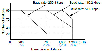
When using a transmission speed of 38.4 kbits/sec. or less, you can set up a maximum of 1,200 m 3,937 ft and 99 units.
For RS422 setting, you can set up a maximum transmission distance of 400 m 1,312 ft.
3)If mixed C-NET adapters are used, up to 32 units can be connected, but transmission speed will be limited to a maximum of 19.2 kbits/sec..
4)The converter SI-35 manufactured by LINE EYE Co., Ltd. is recommendable for the RS485 at the computer side.
When you use the SI-35, please adjust time after FP7 series PLC receives a command until it returns a response by a program.
5)RS422 or RS485 can be selected using the DIP switch built into the communication cassette.
6)Using the DIP switch built into the communication cassette allows the interface to be used as RS232C 5-wire system × 1 channel.
7)1:1 for RS422 interface
| Item | AFP7CCET1 |
|---|---|
| Interface | Ethernet 100Base-TX / 10BASE-T |
| Communication speed | 100 Mbps, 10 Mbps Auto negotiation function |
| Total cable length | 100 m 328.084 ft (500 m 1,640.420 ft when a repeater is used) |
| Number of nodes | Max. 254 units |
| Number of simultaneous connections | Max. 4 connections (User connection: 3, System connection: 1) |
| Communication protocol (Communication layer) | TCP / IP, UDP |
| DHCP | Automatic IP address acquisition |
| General-purpose communication | 4 kB / 1 connection |
| Dedicated communication | Slave communication (MEWTOCOL-COM, MEWTOCOL7-COM, MEWTOCOL-DAT) |
| Master communication (MEWTOCOL-COM, MEWTOCOL7-COM, MEWTOCOL-DAT) |
Notes :
1)Please connect the Ethernet cable with the power turned off.
2)You cannot use this cassette “AFP7CCET1” with the serial communication unit.
| Item | AFP7FCAD2 / AFP7FCA21 | |
|---|---|---|
| Number of input points | 2 channels (non-insulated between channels) | |
| Input range | Voltage | 0 to 10 V / 0 to 5 V *Switch setting (individual settings possible) |
| Current | 0 to 20 mA | |
| Digital conversion value | K0 to K4000 | |
| Resolution | 1/4000 (12 bits) | |
| Conversion speed | 1 ms / channel | |
| Overall precision | ±1 % F.S. or less (0 to 55 ℃ 32 to 131 ℉) | |
| Input impedance | Voltage | 1 MΩ |
| Current | 250 Ω | |
| Absolute maximum input | Voltage | −0.5 V, +15 V |
| Current | +30 mA | |
| Insulation method | ・Between analog input terminal and internal digital circuit: transformer insulation, isolation IC insulation ・Between analog input terminal and analog output terminal: transformer insulation, isolation IC insulation |
|
| Connection method | Connector type terminal block | |
Note : Input specifications of the analog I/O cassette and analog input cassette are the same.
| Item | AFP7FCA21 | |
|---|---|---|
| Number of input points | 1 channel | |
| Output range | Voltage | 0 to 10 V / 0 to 5 V *Switch setting |
| Current | 0 to 20 mA | |
| Digital conversion value | K0 to K4000 | |
| Resolution | 1/4000 (12 bits) | |
| Conversion speed | 1 ms / channel | |
| Overall precision | ±1 % F.S. or less (0 to 55 ℃ 32 to 131 ℉) | |
| Output impedance | 0.5 Ω (voltage output) | |
| Max. output current | 10 mA (voltage output) | |
| Absolute output load resistance | 600 Ω or less (current output) | |
| Insulation method | ・Between analog input terminal and internal digital circuit: transformer insulation, isolation IC insulation ・Between analog input terminal and analog output terminal: transformer insulation, isolation IC insulation |
|
| Connection method | Connector type terminal block | |
Note : There is no analog output functionality in the analog input cassette.
| Item | AFP7FCTC2 | |
|---|---|---|
| Number of input points | 2 channels (insulated between channels) | |
| Input range* |
K type thermocouple | −50.0 to 500.0 ℃ −58.0 to 932.0 ℉ |
| J type thermocouple | −50.0 to 500.0 ℃ −58.0 to 932.0 ℉ | |
| Digital conversion value | Normal time | K−500 to K5000 |
| When range over | K−501, K5001 or K8000 | |
| When the thermocouple broken | K8000 | |
| When data preparation | K8001 | |
| Resolution | 0.2 ℃ 32.36 ℉ (Display is 0.1 ℃ 32.18 ℉ with the software averaging process.) |
|
| Sampling cycle | 100 ms / 2 channels | |
| Overall precision | ± 0.5 % F.S. or less and cold contact accuracy: 1.5 ℃ 34.7 ℉ (0 to 55 ℃ 32 to 131 ℉) |
|
| Input impedance | 344 KΩ | |
| Insulation method | ・Between analog input terminal and internal digital circuit: transformer insulation, isolation IC insulation ・Between analog input terminal and analog output terminal: transformer insulation, isolation IC insulation |
|
| Connection method | Connector type terminal block | |
Note : Thermocouple setting can be switched with the switch on the front of the cassette.
| Item | DC input units | |||
|---|---|---|---|---|
| 16 points type | 32 points type | 64 points type | ||
| Insulation method | Photocoupler | |||
| Rated input voltage | 12 to 24 V DC | 24 V DC | ||
| Rated input current | 6 mA approx. (at 24 V) | 2.7 mA | ||
| Impedance | 3.6 kΩ | 8.2 kΩ | ||
| Min. ON voltage / min. ON current | 9.6 V / 2 mA | 19.2 V / 2.5 mA | ||
| Max. OFF voltage / max. OFF current | 2.5 V / 1 mA | 5 V / 1.5 mA | ||
| Response time |
OFF→ON | 0.1 ms or less | 0.2 ms or less | |
| ON→OFF | 0.2 ms or less | 0.2 ms or less | ||
| Input points per common | 8 points / common | 32 points / common | ||
| Operating mode indicator | 16 points LED display (lights when ON) | 32 points LED display (lights when ON) | ||
| Connection method | Terminal block | 40-pin MIL connectors | ||
Note : Changeable by settable input time constant
| Item | I/O mixed unit (input side) | ||
|---|---|---|---|
| DC input / sink output type | DC input / Source output type | ||
| Insulation method | Photocoupler | ||
| Rated input voltage | 24 V DC | ||
| Rated input current | 2.7 mA | 3.4 mA | |
| Impedance | 8.2 kΩ | 7.5 kΩ | |
| Min. ON voltage / min. ON current | 19.2 V / 2.5 mA | ||
| Max. OFF voltage / max. OFF current | 5 V / 1.5 mA | ||
| Response time |
OFF→ON | 0.2 ms or less (Note) | |
| ON→OFF | 0.2 ms or less (Note) | ||
| Input points per common | 32 points / common | ||
| Operating mode indicator | 32 points LED display (lights when ON, selectable by switch) | ||
| Connection method | 40-pin MIL connectors | ||
Note : Changeable by settable input time constant
| Item | Relay output unit |
Transistor output units | I/O mixed unit (output side) |
||||
|---|---|---|---|---|---|---|---|
| 16 points type | 16 points (NPN) | 32 points (NPN) | 64 points (NPN) | 16 points (PNP) | 32 points (NPN) | ||
| Insulation method | Relay | Photocoupler | Photocoupler | ||||
| Nominal switching capacity |
2 A 250 V AC / 2 A 30 V DC |
– | – | – | – | – | |
| Min. load | 1 mA 100 mV DC (resistive load) |
– | – | – | – | – | |
| Output type | – | Open collector | |||||
| Rated load, voltage |
– | 5 to 24 V DC | |||||
| Operating load voltage range | – | 4.75 to 26.4 V DC | |||||
| Max. load current |
0.3 A (Y0 to Y7) |
– | 1 A | 0.3 A (26.4 to 20.4 V DC) 30 mA (4.75 V DC) |
0.3 A (20.4 to 26.4 V DC) 30 mA (4.75 V DC) |
1 A | 0.3 A (20.4 to 26.4 V DC) 30 mA (4.75 V DC) |
| 0.1 A (all) | – | 0.1 A (20.4 to 26.4 V DC) 15 mA (4.75 V DC) |
0.1 A (20.4 to 26.4 V DC) 15 mA (4.75 V DC) |
||||
| Common restriction | 5 A | 5 A | 3.2 A / common | 5 A | 3.2 A / common | ||
| Max. surge current | – | 3 A | 0.6 A | 3 A | 0.6 A | ||
| OFF state leakage current |
– | 1 μA or less | 1 μA or less | ||||
| ON state voltage drop | – | 0.5 V or less | 0.5 V or less | ||||
| Output points per common | 16 points / common | 16 points / common | 32 points / common | 16 points / common | 32 points / common | ||
| Operation mode indicator | 16 points LED display) | 16 points LED display) | 32 points LED display | 16 points LED display | 32 points LED display | ||
| Connection method | Terminal block | Terminal block | 40-pin MIL connectors | Terminal block | 40-pin MIL connectors | ||
| Item | Transistor output units | I/O mixed unit (output side) | ||
|---|---|---|---|---|
| Source type (PNP open collector) | ||||
| 32 points type | 64 points type | 32 points type | ||
| Insulation method | Photocoupler | |||
| Output type | Open collector | |||
| Rated load voltage | 5 to 24 V DC | |||
| Load voltage allowable range | 4.75 to 26.4 V DC | |||
| Max. load current |
0.3A A (Y0 to Y7) |
0.3 A (26.4 to 20.4 V DC) 30 mA (4.75 V DC) |
0.3 A (20.4 to 26.4 V DC) 30 mA (4.75 V DC) |
|
| 0.1 A (other than that above) |
0.1 A (20.4 to 26.4 V DC) 15 mA (4.75 V DC) |
|||
| Common restriction | 3.2 A/common | |||
| Max. surge current | 0.6 A | |||
| OFF state leakage current |
1 μA or less | |||
| ON state maximum voltage drop | 0.5 V or less | |||
| Repose time |
OFF→ON | 0.1 ms or less (at load current 2 mA or more) | ||
| ON→OFF | 0.5 ms or less (at load current 2 mA or more) | |||
| External power supply |
Voltage | 4.75 to 26.4 V DC | ||
| Current (at 24 V) |
130 mA | 90 mA/common | 90 mA | |
| Surge absorber | Zener diode | |||
| Short circuit protection | – | |||
| Output points per common | 32 points/common | |||
| Operating mode indicator |
32 points LED display (lights when ON) |
32 points LED display (lights when ON, selectable by switch) |
||
| External connection method |
Connector (MIL-compliant 40 pins) |
Connector (MIL-compliant 40 pins, two use) |
Connector (MIL-compliant 40 pins, one use) |
|
| Item | AFP7AD4H | AFP7AD8 | ||
|---|---|---|---|---|
| Number of input channels | 4 | 8 | ||
| Input range (resolution) |
Voltage | -10 to +10 V (resolution: 1/62,500) 0 to 10 V (resolution: 1/31,250) 0 to 5 V (resolution: 1/31,250) 1 to 5 V (resolution: 1/25,000) |
-10 to +10 V (resolution: 1/62,500) 0 to 10 V (resolution: 1/31,250) 0 to 5 V (resolution: 1/31,250) 1 to 5 V (resolution: 1/25,000) (Note) |
|
| Current | 0 to 20 mA (resolution: 1/31,250) 4 to 20 mA (resolution: 1/25,000) |
0 to 20 mA (resolution: 1/31,250) 4 to 20 mA (resolution: 1/25,000) (Note) |
||
| Conversion speed |
Voltage / current | 25 μs/channel (at non-insulated channels) 5 ms/channel (at insulated channels) |
25 μs/channel | |
| Overall accuracy | ± 0.05 % F.S. or less (at 25 ℃77 ℉) ± 0.1 % F.S. or less (at 0 to 55 ℃ 32 to 131 ℉) |
± 0.1 % F.S. or less (at 25 ℃ 77 ℉) ± 0.3 % F.S. or less (at 0 to 55 ℃ 32 to 131 ℉) |
||
| Input | Voltage input | 1 MΩapprox. | ||
| Current input | 250 Ω | |||
| Max. input range | -15 to +15 V DC voltage input -2 to +30 mA current input |
|||
| Insulation method |
Between input terminals and internal circuit |
Photocoupler and isolated DC/DC converter | ||
| Between channels | PhotoMOS relay | – | ||
| Between analog input and isolated DC / DC converter trigger input terminal | – | Photocoupler and isolated DC/DC converter | ||
| Digital processing |
Averaging | Number of times |
Setting range: 2 to 60,000 times | |
| Time duration |
Setting range: 1 to 1,500 ms (at noninsulated channels), 200 to 60,000 ms (at insulated channels) |
Time setting range: 1 to 1,500 ms | ||
| Moving | Setting range: 2 to 2,000 times | |||
| Scale conversion setting | Any value within ±30,000 | |||
| Offset setting | Any value within ±3,000 | |||
| Gain setting | Any value within 9,000 to 11,000 | |||
| Input range change method | Selectable per channel | |||
| Conversion execution / non-execution channel setting | Selectable per channel unit | |||
| Max. and min. value holding | Possible to make settings on a channel-bychannel basis | |||
| Comparison of upper and lower limit values |
Possible to make settings on a channel-bychannel basis (hysteresis) | |||
| Broken wire detection | When less than 2.8 mA (only when current input range 4 to 20 mA is set.) | |||
| Buffer function | 3 trigger types: Soft trigger, External trigger and Input level |
|||
| Trigger input section |
Insulation method | Photocoupler | ||
| Rated input voltage | 24 V DC | |||
| Rated input current | 4.5 mA approx. (at 24 V DC) | 12 mA approx. (at 24 V DC) | ||
| Input impedance | 5.1 kΩ approx. | 2 kΩ approx. | ||
| Operating voltage range | 21.6 to 26.4 V DC | |||
| Min. ON voltage / Min. ON current | 19.2 V / 3.5 mA | |||
| Max. OFF voltage / Max. OFF current | 5 V / 1.5 mA | |||
| Response time |
OFF→ON | 0.2 ms or less | 0.1 ms or less | |
| ON→OFF | 0.2 ms or less | 0.1 ms or less | ||
| Input points per common | 2 points/common | 1 points/common | ||
| Connection method | Terminal block (M3 terminal screw) | – | ||
Note: The full scale (F.S.) on the accuracy of an analog voltage input range from +1 to +5 V and that of an analog current input range from +4 to +20 mA are 0 to +5 V and 0 to +20 mA, respectively.
| Item | AFP7DA4H | |
|---|---|---|
| Number of output channels | 4 | |
| Output range |
Voltage | -10 to +10 V (resolution: 1/62,500) 0 to 10 V (resolution: 1/31,250) 0 to 5 V (resolution: 1/31,250) 1 to 5 V (resolution: 1/25,000) |
| Current | 0 to 20 mA (resolution: 1/31,250) 4 to 20 mA (resolution: 1/25,000) |
|
| Conversion speed |
Voltage / current | 25 μs/channel (at non-insulated channels) 5 ms/channel (at insulated channels) |
| Overall accuracy | ± 0.1% F.S. or less (at 25 ℃ 77 ℉) ± 0.3% F.S. or less (at 0 to 55 ℃ 32 to 131 ℉) |
|
| Output impedance (voltage output) | 0.5 Ω or less | |
| Max. output current (voltage output) | 10 mA | |
| Permissible output load resistance (Current output) |
500 Ω or less | |
| Insulatio method |
Between the input terminals and internal circuit |
Photocoupler and isolated DC/DC converter |
| Between channels | Not insulated | |
| Scale conversion setting | Any value within ± 30,000 | |
| Offset and gain function |
Offset setting | Any value within ± 3,000 |
| Gain setting | Any value within 9,000 to 11,000 | |
| Output range change method | Selectable per channel | |
| Conversion execution/non execution channel setting |
Selectable for one channel | |
| Upper and lower output limit clip function |
Selectable per channel | |
| Analog output holding (in PROG mode) |
Present value/any value/not holding | |
| Connection method | Terminal block (M3 terminal screws) | |
The temperature input units are compatible with the FP7 CPU units with firmware of Ver. 2.0 or later.
The compatible version of Control FPWIN GR7 is 2.2 or later.
| Item | Specifications | ||
|---|---|---|---|
| Number of channels | 8 channels | ||
| Input range (resolution) |
Thermocouple (resolution: 0.1℃ 32.18℉) |
K1:-100.0 to 600.0℃-148.0 to 1112.0℉ / K2:-200.0 to 1000.0℃-328.0 to 1832.0℉ |
|
| J1:-100.0 to 400.0℃-148.0 to 752.0℉ / J2:-200.0 to 750.0℃-328.0 to 1382.0℉ |
|||
| T :-270.0 to 400.0℃-270.0 to 752.0℉ / N :-270.0 to 1300.0℃-270.0 to 2372.0℉ |
|||
| R : 0.0 to 1760.0℃32.0 to 3200.0℉ / S : 0.0 to 1760.0℃32.0 to 3200.0℉ |
|||
| B : 0.0 to 1820.0℃32.0 to 3308.0℉ / E :-270.0 to 1000.0℃-270.0 to 1832.0℉ |
|||
| PLⅡ: 0.0 to 1390.0℃32.0 to 2534.0℉ / WRe5-26:0.0 to 2315.0℃32.0 to 4199.0℉ |
|||
| Voltage | -10 to 10V DC(resolution: 1/62,500) 0 to 5V DC(resolution: 1/31,250) 1 to 5V DC(resolution: 1/25,000)(Note1) -100 to 100mV DC(resolution: 1/62,500) Resolution: max. 16 bits |
||
| Current | 0 to 20 mA (resolution: 1/31,250) 4 to 20 mA (resolution: 1/25,000) (Note 1) Resolution: max. 16 bits |
||
| Conversion speed | 5 ms/channel + 5 ms (Note 2) 25 ms/channel + 25 ms Add the drift compensation measuring time to the number of measuring channels. |
||
| Overall accuracy | ±0.1%F.S.or less(at 25℃77℉) ±0.3%F.S.or less(at 0 to +55℃+32 to +131℉) |
||
| Reference contact compensation accuracy | ±1.0℃33.8℉(with thermocouple input) | ||
| Input impedance |
Voltage / current | 1 MΩ / 250 Ω | |
| Insulation method |
Between input terminals and internal circuit | Photocoupler and isolated DC/DC converter |
|
| Between channels | PhotoMOS relay | ||
| Conversion execution / non-execution channel setting |
Selectable per channel unit | ||
| Input range change method | Selectable per channel | ||
| Digital processing |
Averaging | Cycle, time, moving | |
| Scale conversion setting | Any value within ±30,000 (Voltage and current range only) | ||
| Offset setting | Any value within ±3,000 | ||
| Gain setting | ±10% | ||
| Comparison of upper and lower limit values | Selectable for one channel | ||
| Max. and min. value holding | Selectable for one channel | ||
| Broken wire detection | Available | ||
| Connection method | Connector type terminal block | ||
Notes :
1)The full scale (F.S.) ranges of accuracy are 1 to 5 V DC for voltage and 0 to 20 mA for current input, respectively.
2)The AC noise removal is disabled.
| Item | Specifications | ||
|---|---|---|---|
| Number of channels | 8 channels | ||
| Input range (resolution) |
Resistance temperature detector (resolution: 0.1℃32.18℉) |
Pt100 (1): -100.0 to 200.0℃-148.0 to 392.0℉ Pt100 (2): -200.0 to 650.0℃-328.0 to 1202.0℉ JPt100(1): -100.0 to 200.0℃-148.0 to 392.0℉ JPt100(2): -200.0 to 650.0℃-328.0 to 1202.0℉ Pt1000: -100.0 to 100.0℃-148.0 to 212.0℉ |
|
| Conversion speed | 25 ms/channel + 25 ms Add the drift compensation measuring time to the number of measuring channels. |
||
| Overall accuracy | ±0.1%F.S.or less(at 25℃77℉) ±0.3%F.S.or less(at 0 to +55℃+32 to +131℉) |
||
| Allowable signal source resistance | R.T.D. input: 30 Ω(three wires balanced) | ||
| Insulation method |
Between input terminals and internal circuit |
Photocoupler and isolated DC/DC converter |
|
| Between channels | PhotoMOS relay | ||
| Conversion execution / non-execution channel setting |
Selectable per channel unit | ||
| Input range change method | Selectable per channel | ||
| Digital processing |
Averaging | Cycle, time, moving | |
| Offset setting | Any value within ±3,000 | ||
| Gain setting | ±10% | ||
| Comparison of upper and lower limit values | Selectable for one channel | ||
| Max. and min. value holding | Selectable for one channel | ||
| Broken wire detection | Available | ||
| Connection method | Connector type terminal block | ||
| Type | 2 ch type | 4 ch type | ||
|---|---|---|---|---|
| Model No. | AFP7HSC2T | AFP7HSC4T | ||
| Input | Insulation method | Photocoupler | ||
| Rated input voltage | 12 to 24 V DC / 3.5 to 5 V DC | |||
| Input impedance |
24 V DC | 3.0 kΩ approx. | ||
| 5 V DC | 390 Ω approx. | |||
| Usage voltage range | 24 V DC | 10.8 to 26.4 V DC | ||
| 5 V DC | 3.5 to 5.25 V DC | |||
| Min. ON voltage / Min. ON current |
24 V DC | 10 V DC / 4 mA | ||
| 5 V DC | 3.0 V DC / 4 mA | |||
| Min. OFF voltage / Min. OFF current |
24 V DC | 2.0 V DC / 2 mA | ||
| 5 V DC | 1.0 V DC / 0.5 mA | |||
| Input time constant setting | None, 0.1 μs, 0.2 μs, 0.5 μs, 1.0 μs, 2.0 μs, 10.0 μs | |||
| Count function |
No. of counters | 2 ch | 4 ch | |
| Counter type | Linear counter / Ring counter | |||
| Counting range | Signed 32-bit ( -2,147,483,648 to +2,147,483,647 ) | |||
| Max. input frequency | 4 MHz / 8 MHz for individual input (phases A and B) (Duty ratio 50 ± 10 %) 4 MHz / 8 MHz for direction discrimination input (Duty ratio 50 ± 10 %) 4 MHz / 8 MHz /16 MHz for 2-phase input (Duty ratio 50 ± 10 %, Phase shifting below 5 %) |
|||
| Input signal | Phases A, B and Z | |||
| External I/O | Control signal input: 4 points (2 points/ch) External output: 4 points (2 points/ch) |
Control signal input: 8 points (2 points/ch) External output: 8 points (2 points/ch) |
||
| Counter input type | Individual input: 1 multiple, 2-multiple Direction discrimination input: 1 multiple, 2-multiple 2-phase input: 1 multiple, 2-multiple, 4-multiple |
|||
| Measurement function |
Frequency measurement function | Measures the intervals between the variations of count values, and calculates the frequency. | ||
| Comparison function |
Target value match function | Depending on the count direction, sets or resets the output when the counter value reaches the target value. | ||
| External output |
Comparison result output function | Outputs the result of comparison function. | ||
| Other functions |
Capture function | Acquires the current count value from the edges of input signals, and stores it in the capture 0 register or capture 1 register. The value of the specified capture register will be overwritten by a new value and the old value will be discarded every time a counter value is captured. | ||
| Interrupt input function | Available (2 points/ch, Max. 8 points/unit) (Note 1, 2) | |||
Notes :
1)The interrupt input function can be used for 8 points per unit and for a maximum of 8 units (max. 64 points) in the whole system. However, the entire scan time slows down as more interrupt programs are used. Minimize the use of interrupt programs.
2)The priority order for interrupt inputs is as follows; In a unit, from the smallest interrupt bit. In the whole system, from the smallest unit number. from the smallest unit number.
| Item | Specifications | |||||||
|---|---|---|---|---|---|---|---|---|
| 2 axes type | 4 axes type | |||||||
| Part No. | AFP7PP02T | AFP7PP02L | AFP7PP04T | AFP7PP04L | ||||
| Output type | Transistor | Line driver | Transistor | Line driver | ||||
| Max. operation speed | 500 kpps | 4Mpps | 500kpps | 4Mpps | ||||
| Number of axes controlled | 2 axes linear interpolation and 2 axes circular interpolation | 2 axes linear interpolation, 2 axes circular interpolation, 3 axes linear interpolation and 3 axes spiral interpolation |
||||||
| Acceleration & deceleration time | 0 to 10,000 ms for automatic & manual operation (JOG operation & home return) |
|||||||
| Acceleration & deceleration method | Linear acceleration / deceleration, S-curve acceleration / deceleration for automatic & manual operation (JOG operation) |
|||||||
| Automatic operation |
Position control |
Position command method | Absolute / relative | |||||
| Number of positioning tables per axis | Standard area: 600 points, expansion area: 25 points | |||||||
| Control method | Independent | For each axis; standard area: 600 points, expansion area: 25 points | ||||||
| 2-axis inter- polation |
Linear | E point, P point and C point controls: master axis speed | ||||||
| Circular | E point, P point and C point controls: center point or passing point |
|||||||
| 3-axis inter- polation |
Linear | E point, P point and C point controls | ||||||
| Spiral | E point, P point and C point controls: center point or passing point |
|||||||
| Startup time | Standard area: 3 ms or less, expansion area: 5 ms or less |
|||||||
| Other function | Dwell time | 0 to 32,767 ms (in increments of 1 ms) | ||||||
| Manual operation | Home return | Acceleration & deceleration method | Linear acceleration / deceleration | |||||
| Return methods | 7 methods | |||||||
| Pulser operation | Speed command | Range operates in synchronization with pulser input | ||||||
| Stop function | Deceleration stop, emergency stop, limit stop, error stop, system stop | |||||||
| Synchronous operation function |
Synchronous basic setting |
Master axis | Existing axes, virtual axes or pulse input (1 to 4) | |||||
| Slave axis | Max. 2 axes | Max. 4 axes | ||||||
| Electronic gear & clutch function | Yes | |||||||
| Electronic cam function |
Cam curve | Select from 20 types | ||||||
| Resolution | 1024, 2048, 4096, 8192, 16384, 32768 | |||||||
| Number of cam patterns | 4 to 16 | |||||||
| Other specifications | Output mode | 1 pulse output (pulse + direction), 2 pulse outputs (CW / CCW) |
||||||
| High-speed counter function |
Countable range | −1,073,741,823 to +1,073,741,823 pulse | ||||||
| Input mode | Two-phase input, incremental/decremental control input, individual input (with multiplier function mode) | |||||||
| Built-in servo ON output | Two-phase input, incremental/decremental control input, individual input (with multiplier function mode) | |||||||
| Item | Specifications | ||||
|---|---|---|---|---|---|
| Part No. | AFP7PG02T | AFP7PG04T | AFP7PG02L | AFP7PG04L | |
| Output type | Transistor | Line driver | |||
| Occupied points | Each 32 points of I/O | Each 64 points of I/O | Each 32 points of I/O | Each 64 points of I/O | |
| Number of axes controlled | 2 axes, independent | 4 axes, independent | 2 axes, independent | 4 axes, independent | |
| Position command | Command units | Pulse (The program specifies whether increment or absolute is used.) | |||
| Max. pulse count | Signed 32 bits (+2,147,483,647 to -2,147,483,648 pulses) | ||||
| Speed command | Command range | 1 pps to 500 kpps (can set in 1 pps) | 1 pps to 4 Mpps (can set in 1 pps) | ||
| Acceleration/ deceleration command |
Acceleration / deceleration |
Linear acceleration / deceleration, S acceleration / deceleration | |||
| “S” Acceleration / deceleration |
Can select from sin curve, secondary curve, cycloid curve and third curve. | ||||
| Acceleration / deceleration time |
0 to 32,767 ms (can set in 1 ms) | ||||
| Home return | Home return speed | Speed setting possible (changes return speed and search speed) | |||
| Input signal | Home input, near home input, limit input (+), limit input (−) | ||||
| Output signal | Deviation counter clear signal | ||||
| Operation mode | ・E point control (linear and s acceleration/decelerations) ・P point control (linear and s acceleration/decelerations) ・Home return operation (home search) ・JOG operation (Note 1) ・JOG positioning operation ・Pulser input function (Note 2) transfer multiplication ratio (× 1, × 2, × 5, × 10, × 50, × 100, × 500, × 1000) ・Real-time frequency change ・Infinity output |
||||
| Startup time | 0.02 ms, 0.005 ms or 0.001 ms selecting possible (Note 3) | ||||
| Output interface | Output mode | 1 pulse output (pulse and sign), 2 pulse output (CW and CCW) | |||
| High-speed counter function (Note 2) |
Countable range | Signed 32 bits (+2,147,483,647 to -2,147,483,648 pulse) | |||
| Input mode | Two-phase input, direction distinction input, individual input (with multiplier function mode) | ||||
| Other functions | ・Startup using I/O contact ・Built-in limit (+) and limit (−) ・With servo ON output |
||||
| External power supply | Voltage | 21.6 to 26.4 V DC | |||
| current | 50 mA (at 24 V) | 90 mA (at 24 V) | 50 mA (at 24 V) | 90 mA (at 24 V) | |
Notes :
1)When linear acceleration/deceleration operation is selected, it is possible to change the target speed during operation.
2)Since the pulsar input function and the high-speed counter function use the same pulse input terminal, both functions cannot be used at the same time.
3)Startup time can be changed using the common memory control code setting. The factory (default) setting is 0.02 ms. Startup time is defined as the time between startup and output of the first pulse.
| Item | Specifications | |
|---|---|---|
| Part No. | AFP7PSA1 | AFP7PSA2 |
| Rated input voltage | 100 to 240 V AC | |
| Allowable input voltage range | 85 to 264 V AC | |
| Input power supply frequency | 47 to 63 Hz | |
| Inrush current | 40 A or less (Note 2) | |
| Input current | 0.75 A or less | 1.25 A or less |
| Rated output current (at 24 V) | 1.0 A | 1.8 A |
| Alarm contact capacity | 1 A (30 V DC) | |
| Remaining lifespan counter | Not available | Available (Note 1) |
Notes :
1)Alarm by CPU unit
2)On cold starting
3)Power supply unit cannot be used with AFP7CPS21 CPU unit.
| Item | AFP7NSC |
|---|---|
| Number of communication cassette installations | Max. 2 cassettes |
| Number of installations to CPU unit | Max. 8 units |
Note : Ethernet cassette is not supported.
| Item | Specifications |
|---|---|
| Communication method | Two-wire system half duplex |
| Insulation method | Pulse transformer insulation |
| Communication speed | 6 Mbps / 12 Mbps |
| Synchronous method | Bit synchronization |
| Error check | CRC-12 |
| Communication distance | Total length 200 m 656 ft (at 6 Mbps) / 100 m 328 ft (at 12 Mbps) (Note) |
| Connection method | Multi-drop method |
| Impedance | 100 Ω |
| Terminator | Mounted on unit |
| External interface | Master unit: terminal block (2 channels) Slave unit (standard type): screw-type terminal block Slave unit (compact type): connector-type terminal block |
Note : Performance when the recommended cable is used Use of the recommended cable is necessary to achieve the maximum transmission distance and number of slave units.
| Item | Specifications | ||
|---|---|---|---|
| Standard type | Compact type | ||
| Insulation method | Photocoupler | Non-isolated | |
| Rated input voltage | 24 V DC | ||
| Rated input current | 3 mA approx. | 4.3 mA approx. | |
| Input impedance | 7.5 kΩ approx. | 5.6 kΩ approx. | |
| Min. ON voltage / Min. ON current | 15 V / 2 mA | 17 V / 2 mA | |
| Max. OFF voltage / Max. OFF current | 5 V / 0.5 mA | ||
| Response time | OFF→ON | 1 ms or less | |
| ON→OFF | 1 ms or less | ||
Please note that standard type AFPRP1□ conforms to EMC Directive when used with recommended cable as below (except for AFPRP2□).
ZHY221PS made by Shinko Seisen Industry Co., Ltd.
Characteristics
Note : If the recommended cable is not used, it may not be possible to reach the maximum transfer distance or performance with the maximum number of slaves. Please configure the wiring collinearly on all system.
| Item | Specifications | ||
|---|---|---|---|
| Standard type | Compact type (except relay) |
||
| Insulation method | Photocoupler | Non-isolated | |
| Output type | Sink type (Open collector output) | ||
| Rated load voltage | 20.4 to 28.8 V DC | ||
| Max. control capacity | 0.1 A/point | ||
| Max. surge current | 0.5 A | ||
| OFF state leakage current | 0.1 mA or less | ||
| ON state maximum voltage drop | 0.5 V or less | ||
| Repose time | OFF→ON | 0.05 ms or less | |
| ON→OFF | 0.5 ms or less | ||
| Surge absorber | Zener diode | ||
| Short circuit protection | None | ||
| Item | Specifications | |
|---|---|---|
| Compact type (relay) | ||
| Insulation method | Relay insulation | |
| Rated control capacity | 1 A 250 V AC (2 A/common) 1 A 30 V DC (2 A/common) |
|
| Min. load | 0.1 mA 100 mV (resistive load) | |
| Repose time | OFF→ON | 10 ms or less |
| ON→OFF | 5 ms or less | |
| Life time | Mechanical life | 2 × 10⁷ operations or more |
| Electrical life | 1 × 10⁵ operations or more (switching frequency: 20 times/minute) |
|
| Surge absorber | None | |
| Short circuit protection | None | |
| Item | Specifications |
|---|---|
| Ambient temperature | 0 to +55 ℃ +32 to +131 ℉, at storage: -40 to +70 ℃ -40 to +158 ℉ |
| Ambient humidity | 10 to 95 % RH (at 25 ℃ 77 ℉, no condensation), at storage: 10 to 95 % RH (at 25 ℃ 77 ℉, no condensation) |
| Breakdown voltage | 500 V AC for 1 minute (Note 2) (Note 3) |
| Insulation resistance | 100 MΩ or more (at 500 V DC) |
| Vibration resistance | 5 to 8.4 Hz, single amplitude of 3.5 mm 0.138 in, 1 sweep/min. (IEC61131-2); 8.4 to 150 Hz, constant acceleration of 9.8 m/s2, 1 sweep/min. (IEC61131-2), 10 times each in X, Y, and Z directions |
| Shock resistance | 147 m/s2 or more , 3 times each in X, Y, and Z directions (IEC61131-2) |
| Noise immunity | 1,000 V [p-p] with pulse width 50 ns and 1 μs (using a noise simulator) |
| Operating condition | Free from corrosive gasses and excessive dust |
Notes :
1)Please refer to the unit’s specification sheet for details of breakdown voltage and insulation resistance.
2)Relay output of input and output unit: 2,300 V AC for 1 minute
3)Between analog input channels of analog input unit: 200 V AC for 1 minute. Between channels of output unit: non insulation
| Item | CPU units | Expansion units | ||||
|---|---|---|---|---|---|---|
| AFP7CPS41E(S) | AFP7CPS31E(S) | AFP7CPS31(S) | AFP7CPS21 | AFP7EXPM | AFP7EXPS | |
| Rated voltage range | 20.4 to 28.8 V DC | – | 20.4 to 28.8 V DC | |||
| Current consumption | 200 mA or less | 150 mA or less | 120 mA or less (Note 1) |
100 mA or less (Note 1) |
||
| Net weight | 220 g approx. (with terminal block and end unit) |
180 g approx. (with terminal block and end unit) |
120 g approx. | 200 g approx. (with end unit) |
||
| Item | Communication cassettes | |||||
|---|---|---|---|---|---|---|
| AFP7CCS1 | AFP7CCS2 | AFP7CCM1 | AFP7CCM2 | AFP7CCS1M1 | AFP7CCET1 | |
| Rated voltage range | – | – | – | – | – | – |
| Current consumption | 35 mA or less (Note 2) |
60 mA or less (Note 2) |
60 mA or less (Note 2) |
90 mA or less (Note 2) |
70 mA or less (Note 2) |
35 mA or less (Note 2) |
| Net weight | 25 g approx. (with terminal block) | 20 g approx. | ||||
| Item | Function cassettes | Power supply units | Serial communication unit | |||
|---|---|---|---|---|---|---|
| AFP7FCAD2 | AFP7FCA21 | AFP7FCTC2 | AFP7PSA1 | AFP7PSA2 | AFP7NSC | |
| Rated voltage range | – | – | – | 100 to 240 V AC | – | |
| Current consumption | 40 mA or less (Note 2) |
75 mA or less (Note 2) |
45 mA or less (Note 2) |
750 mA or less | 1,250 mA or less | 50 mA or less |
| Net weight | 25 g approx. (with terminal block) | 240 g approx. | 290 g approx. | 110 g approx. | ||
| Item | Input and output units | ||||
|---|---|---|---|---|---|
| AFP7X16DW | AFP7X32D2 | AFP7X64D2 | AFP7Y16R | AFP7Y16T | |
| Rated voltage range | – | – | – | – | – |
| Current consumption | 25 mA or less | 30 mA or less | 35 mA or less | 180 mA or less | 35 mA or less |
| Net weight | 125 g approx. | 95 g approx. | 110 g approx. | 180 g approx. | 125 g approx. |
| Item | Input and output units | ||||
|---|---|---|---|---|---|
| AFP7Y32T | AFP7Y64T | AFP7Y16P | AFP7Y32P | AFP7Y64P | |
| Rated voltage range | – | – | – | – | – |
| Current consumption | 50 mA or less | 75 mA or less | 35 mA or less | 50 mA or less | 75 mA or less |
| Net weight | 95 g approx. | 115 g approx. | 125 g approx. | 95 g approx. | 115 g approx. |
| Item | Input and output units | Analog input and output units | |||
|---|---|---|---|---|---|
| AFP7XY64D2T | AFP7XY64D2P | AFP7AD8 | AFP7AD4H | AFP7DA4H | |
| Rated voltage range | – | – | – | – | – |
| Current consumption | 55 mA or less | 55 mA or less | 85 mA or less | 100 mA or less | 250 mA or less |
| Net weight | 115 g approx. | 115 g approx. | 130 g approx. | 130 g approx. | 130 g approx. |
Note: Increased CPU unit current consumption
| Item | Temperature input units | |
|---|---|---|
| AFP7TC8 | AFP7RTD8 | |
| Rated voltage range | – | – |
| Current consumption | 80 mA or less | 65 mA or less |
| Net weight | 145 g approx. | 145 g approx. |
| Item | Positioning units | High-speed counter units | ||||
|---|---|---|---|---|---|---|
| AFP7PP02T | AFP7PP04T | AFP7PP02L | AFP7PP04L | AFP7HSC2T | AFP7HSC4T | |
| Rated voltage range | – | – | – | – | – | – |
| Current consumption | 120 mA or less | 120 mA or less | 120 mA or less | 120 mA or less | 65 mA or less | |
| Net weight | 145 g approx. | 145 g approx. | 145 g approx. | 145 g approx. | 130 g approx. | |
| Item | Pulse output units | |||
|---|---|---|---|---|
| AFP7PG02T | AFP7PG04T | AFP7PG02L | AFP7PG04L | |
| Rated voltage range | – | – | – | – |
| Current consumption | 65 mA or less | 65 mA or less | 65 mA or less | 65 mA or less |
| Net weight | 130 g approx. | 150 g approx. | 130 g approx. | 150 g approx. |
| Item | PHLS (remote I/O) units | ||||
|---|---|---|---|---|---|
| AFP7PHLSM | AFPRP1X08D2 | AFPRP1X16D2 | AFPRP1Y16T | AFPRP1XY16D2T | |
| Rated voltage range | – | 20.4 to 28.8 V DC | |||
| Current consumption | 85 mA or less | 100 mA or less | 150 mA or less | 75 mA or less | 120 mA or less |
| Net weight | 110 g approx. | 140 g approx. | 210 g approx. | 210 g approx. | 210 g approx. |
| Item | PHLS (remote I/O) units | ||||
|---|---|---|---|---|---|
| AFPRP2X08D2E | AFPRP2X16D2 | AFPRP2Y16T | AFPRP2XY16D2T | AFPRP2Y04R | |
| Rated voltage range | 20.4 to 28.8 V DC | ||||
| Current consumption | 100 mA or less | 170 mA or less | 40 mA or less | 110 mA or less | 85 mA or less |
| Net weight | 75 g approx. | 75 g approx. | 75 g approx. | 75 g approx. | 75 g approx. |
Note :
1)Differs depending on power supply voltage and number of expansion units.
2)This value is the increase in CPU current consumption.