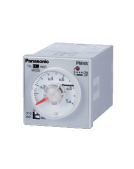
Upgraded KT4 models
Improved visibility, operability and performance!
UL/C-UL , CE Approved
CE : EMC Directive
UL : Recognition
Operation startup can begin after using initial setting mode to enter the control values required before first use, and after entering values for items such as frequently used and frequently changed settings.
Smooth operation is enabled at initial startup and after changing settings.
Easy programmed control made possible using nine-step setting procedure. By entering specific target values for each indicated period, freely selectable temperature control is possible.
Example: From start of programmed control
(1):Perform control so it becomes 200 ℃ 392 ℉ after 1 hour.
(2):Maintain 200 ℃ 392 ℉ until after 2 hours
(3):Perform control so it becomes 300 ℃ 572 ℉ after 30 minutes.

Sampling period rate half (1/2 times) from previous model: high speed 125 ms processing implemented. With twice the responsiveness, it is possible to more finely carry out control, for example, of the heat capacity.
The built-in rearing auto tuning function uses the step response method. From temperature rise behavior alone, it can calculate the PID constants. It is possible to calculate constants, even when auto tuning cannot be used to generate them.
Because an ON / OFF operation is unnecessary, there is no disruption in control.

Versatile thermocouple, RTD, DC voltage and DC current input for temperature detecting sensors.
All required operations can be enabled by the front keys and highly accurate PID control mode ensures an input span of ±0.2 %.
The KT series offers both economy and high performance.
(Sample System Configuration)

*1 : Only on type equipped with communications function.
*2 : In the configuration above, the FPΣ requires a communication cassette (FPG-COM3).
*3 : Modbus protocol is a communication protocol developed for PLCs by Modicon Inc.
| Item | Specifications | ||||
|---|---|---|---|---|---|
| Size | 48×48mm 1.890 × 1.890 in | ||||
| Rating | Rating power supply (Must be specified) |
100 to 240V AC | |||
| 24V AC / DC | |||||
| Rating frequency | 50 / 60Hz | ||||
| Rating power consumption | 8 VA approx. | ||||
| Rating scale |
Input type | Input range | |||
| Thermocouple | K | -200 to 1,370℃ (-328 to 2,489℉) | |||
| -200.0 to 400.0℃ (-328.0 to 752.0℉) | |||||
| J | -200 to 1,000℃ (-328 to 1,832℉) | ||||
| R | 0 to 1,760℃ (0 to 3,200℉) | ||||
| S | 0 to 1,760℃ (0 to 3,200℉) | ||||
| B | 0 to 1,820℃ (32 to 3,308℉) | ||||
| E | -200 to 800℃ (-328 to 1,472℉) | ||||
| T | -200.0 to 400.0℃ (-328.0 to 752.0℉) | ||||
| N | -200 to 1,300℃ (-328 to 2,372℉) | ||||
| PL-II | 0 to 1,390℃ (32 to 2,534℉) | ||||
| C (W / Re5−26) |
0 to 2,315℃ (32 to 4,199℉) | ||||
| RTD | Pt100 | -200 to 850℃ (-328 to 1,562℉) | |||
| -200.0 to 850.0℃ (-328.0 to 1,562.0℉) | |||||
| JPt100 | -200 to 500℃ (-328 to 932℉) | ||||
| -200 to 500.0℃ (-328.0 to 932.0℉) | |||||
| DC | Current | 4 to 20 mA DC | -2,000 to 10,000 | ||
| 0 to 20 mA DC | |||||
| Voltage | 0 to 1 V DC | ||||
| 0 to 10 V DC | |||||
| 1 to 5 V DC | |||||
| 0 to 5 V DC | |||||
| ・Scaling and change to the decimal point position is possible for DC current input and DC voltage input. | |||||
| Multi- input |
Thermocouple | K, J, R, S, B, E, T, N, PL-II, C (W / Re5-26) External resistor: Max. 100 Ω (Max. 40 Ω external resistor for B input) |
|||
| RTD | Pt100, JPt100 3-conductor system (Allowable input conductor resistance for each conductor: Max. 10 Ω) | ||||
| DC current | 0 to 20 mA DC | Input impedance: 50 Ω Allowable input current: Max. 50 mA |
|||
| 4 to 20 mA DC | |||||
| DC voltage | 0 to 1 V DC | Input impedance: Min. 1 MΩ, Allowable input voltage: Max 5 V, Allowable signal source resistance: Max. 2 kΩ | |||
| 0 to 5 V DC | Input impedance: Min. 100 kΩ, Allowable input voltage: Max 15 V, Allowable signal source resistance: Max. 100 Ω |
||||
| 1 to 5 V DC | |||||
| 0 to 10 V DC | |||||
| Control output |
Relay contact | (Must be specified) |
1a | ||
| 3 A 250 V AC (at resistive load), 1 A 250 V AC (at inductive load cos ø = 0.4), Electrical life: 100,000 times | |||||
| Non-contact voltage (voltage output for SSR drive) |
12+20 V DC, Max. load current: 40 mA (with short circuit protection circuit) | ||||
| DC current | 4 to 20 mA DC, Load resistance: Max. 550 Ω | ||||
| Alarm output 1 (EV1) | Relay contact 1a 3 A 250 V AC (Resistive load) 1a 1 A 250 V AC (cosø=0.4) Electrical life: 100,000 times |
||||
| Alarm output 2 (EV2) | Same as Alarm output 1 | ||||
| Control method | PID action (with auto-tuning function), PI action, PD action (with manual reset function), P action (with manual reset function), ON / OFF action | ||||
| Target temperature setting | – | ||||
| Program control function | 1 pattern, 9-step setting is possible (However, make function selection setting of either control with fixed set point or program control.) | ||||
| Indication accuracy |
Thermocouple | Within ± (0.2 % + 1 digit) of each input span or within ±2 ℃ (4 ℉) whichever is greater However, R or S input; within ±6 ℃ (12 ℉) in the range of 0 to 200 ℃ (32 to 392 ℉) B input, range of 0 to 300 ℃ (32 to 572 ℉): accuracy is not guaranteed. K, J, E, T, and N input, less than 0 ℃ (32 ℉): within ± (0.4 % ±1 digit) of input span |
|||
| RTD | Within ± (0.1 % + 1 digit) of each input span or ±1 ℃ (2 ℉) whichever is greater | ||||
| DC current and DC voltage | Within ± (0.2 % + 1 digit) of each input span | ||||
| Sampling period | 125ms | ||||
| Hysteresis (ON / OFF) | Thermocouple and RTD: 0.1 to 1,000.0 ℃ (℉) DC current and DC voltage: 1 to 10,000 (The decimal point place follows the selection) |
||||
| Proportional band | Input without decimal point: 0 to Input span Input with decimal point: 0.0 to Input span DC current and DC voltage: 0.0 to 1,000.0 % |
||||
| Integral time | 0 to 3,600 seconds | ||||
| Derivative time | 0 to 1,800 seconds | ||||
| Proportional cycle | 1 to 120 seconds | ||||
| Allowable voltage fluctuation | When 100 to 240 V AC: 85 to 264 V AC, When 24 V AC / DC: 20 to 28 V AC / DC | ||||
| Insulated resistance | 500 V DC, Min. 10 MΩ | ||||
| Breakdown voltage | Between input terminal and power terminal Between output terminal and power terminal 1.5 kV AC for 1 min. |
||||
| Malfunction vibration | 10 to 55 Hz (1 cycle/min.), single amplitude: 0.35 mm 0.014 in (10 min. on 3 axes) | ||||
| Breakdown vibration | 10 to 55 Hz (1 cycle/min.), single amplitude: 0.75 mm 0.030 in (1 hour on 3 axes) | ||||
| Malfunction shock | X, Y and Z each direction for 5 times 98 m/s2 | ||||
| Breakdown shock | X, Y and Z each direction for 5 times 294 m/s2 | ||||
| Ambient temperature | −10 to 55 ℃ 14 to 131 ℉ | ||||
| Ambient humidity | 35 to 85 % RH (No condensation) | ||||
| Mass | 110 g approx. | ||||
| Waterproof | IP66 (applicable only to the front panel subject to rubber gasket employed) | ||||
| Display character height | PV: 12.4 mm 0.488 in SV: 8.8 mm 0.346 in |
||||
| Option functions |
Heating / Cooling control |
Relay contact | Using EV2 assigned setting, use for heating and cooling control is possible. | ||
| Non-contact voltage |
– | ||||
| Heater burnout alarm output |
– | ||||
| Communication function | Please refer below to “COMMUNICATION PERFORMANCE OUTLINE”. | ||||
| Accessories | Installation frame / Mounting bracket |
Included with controller | |||
| Terminal cover | Sold separately | ||||
| Rubber gasket | Included with controller | ||||
| Item | Specifications |
|---|---|
| Communication method | Half-duplex |
| Communication speed | Select 9600, 19200 or 38400 bps using key operation. |
| Synchronous method | Asynchronous |
| Protocol | Modbus (RTU, ASCII), MEWTOCOL (Slave) |
| Coding | Binary / ASCII |
| Error correcting | Command resending |
| Error detection | Parity check and check sum |
| Data structure | Start bit: 1 Data bit: 7, 8 (For Modbus RTU: 8 only) Parity: Even / Odd / None Stop bit: 1 or 2 |
| Interface | EIA RS485 compliant |
| Number of nodes | 31 |
| Maximum communication distance | 1,000 m 3,280.840 ft (cable resistance must be within 50 Ω) |
Improved model of existing GT32M/T !!!
UL/C-UL , CE Approved CE : EMC Directive UL : Approved Listing