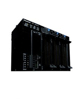
DIN 48 SIZE LCD ELECTRONIC COUNTER
UL/C-UL , CE Approved
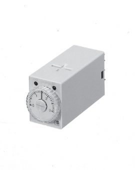
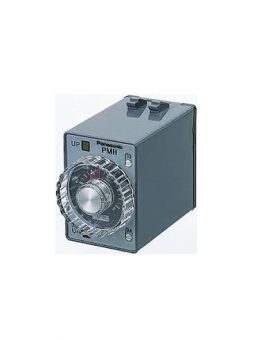
| 4-digit display | Pin type | Screw terminal type |
|---|---|---|
 |
 |
 |
All this at an affordable price to provide you with unmatched cost performance.
Set the input and output modes with the DIP switches on the side of the counter.

Set the set value with the UP and DOWN keys on the front of the counter.
4-digit display type
|
 |
6-digit display type
|
 |
For the input mode, you can choose one of the following five modes
| Input mode | Operation | *Minimum input signal width 30 Hz: 16.7 ms; 5 kHz: 0.1 ms |
|---|---|---|
| Addition [UP] |
IN1 or IN2 works as an input block (gate) for the other input. | Example where IN1 is the count counting and IN2 is the input block (gate). Example where IN2 is the counting input and IN1 is the input block (gate).  *”A” must be more than the minimum input signal width. |
| Subtraction [DOWN] |
||
| Directive [DIR] |
IIN1 is the counting input and IN2 is the addition or subtraction directive input. IN2 adds at L level and subtracts at H level. |  * “A” must be more than the minimum input signal width. |
| Independent [IND] |
IN1 is addition input and IN2 is subtraction input. |  IN1 and IN2 are completely independent, so there is no restriction on signal timing. |
| Phase [PHASE] |
Addition when the IN1 phase advances beyond IN2, and subtraction when the IN2 phase advances beyond IN1. |  * “B” must be more than the minimum input signal width. |
For the output mode, you can choose one of the following seven modes
| Output mode | Operation | (Example when input mode is either addition or subtraction) |
|---|---|---|
| Maintain output Hold count [HOLD-A] |
Output control is maintained after count-up completion and until resetting. During that time, the count display does not change from that at count-up completion. |  *n:Set value |
| Maintain output Over count I [HOLD-B] |
Output control is maintained after count-up completion and until resetting. However, counting is possible despite completion of count-up. |  *n:Set value |
| Maintain output Over count II [HOLD-C] |
Output control is maintained after count-up completion and until the next signal enters. However, counting is possible despite completion of countup. |  *n:Set value |
| One shot Over count [SHOT-A] |
Output control is maintained after count-up completion for a fixed time (approx. 1 sec). Counting is possible despite completion of count-up. |  *n:Set value |
| One shot Recount I [SHOT-B] |
Output control is maintained after count-up completion for a fixed time (approx. 1 sec). Counting is possible despite completion of count-up. However, reset occurs simultaneous with completion of count-up. While output is being maintained, restarting of the count is not possible |  *n:Set value |
| One shot Recount II [SHOT-C] |
Output control is maintained after count-up completion for a fixed time (approx. 1 sec). Counting is possible despite completion of count-up. However, reset occurs simultaneous with output OFF. |  *n:Set value |
| One shot Hold count [SHOT-D] |
Output control is maintained after count-up completion for a fixed time (approx. 1 sec). During that time, the count display does not change from that at count-up completion. Reset occurs simultaneous with output OFF. |  *n:Set value |
| Type | Ralay output type | Transistor output type | ||||
|---|---|---|---|---|---|---|
| Item | AC type | DC type | AC type, AC/DC type | DC type | ||
| Rating | Rated operating voltage | 100 to 240 V AC, 24 V AC | 12 to 24 V DC | 100 to 240 V AC, 24 V AC, 24 V AC/DC | 12 to 24 V DC | |
| Rated frequency | 50/60 Hz common | – | 50/60 Hz common | – | ||
| Rated power consumption | Max. 10 V A | Max. 3 W | Max. 10 V A | Max. 3 W | ||
| Rated control capacity | 5 A 250 V AC (resistive load) | 100 mA 30 V DC | ||||
| Input mode | Addition (UP)/Subtraction (DOWN)/Direction (DIR)/Individuality (IND)/Phase (PHASE) 5 modes selectable by DIP switch |
|||||
| Max. counting speed | 30 Hz/5 kHz (selectable by DIP switch) | |||||
| Counting input (Input 1, 2) | Min. input signal width: 16.7 ms at 30 Hz/0.1 ms at 5 kHz, ON time: OFF time = 1:1 | |||||
| Reset input | Min. input signal width: 1 ms, 20 ms (selected by DIP switch) | |||||
| Lock input | Min. input signal width: 20 ms | |||||
| Input signal | Contact or Open collector input/Input impedance: 1 kΩ or less, Input residual voltage: 2 V or less, Open impedance: 100 kΩ or more, Max. energized voltage: 40 V DC |
|||||
| Output mode | HOLD-A/HOLD-B/HOLD-C/SHOT-A/SHOT-B/SHOT-C/SHOT-D (7 modes selectable by DIP switch) | |||||
| One shot output time | Approx. 1 s | |||||
| Indication | 7-segment LCD, Counter value (backlight red LED), Setting value (backlight yellow LED) | |||||
| Digit | 4-digit display type –999 to 9999 (–3 digits to +4 digits) (0 to 9999 for setting) 6-digit display type –99999 to 999999 (–5 digits to 6 digits) (0 to 999999 for setting) |
|||||
| Memory | EEP-ROM (Overwriting times: 105 ope. or more) | |||||
| Contact | Contact arrangement | Relay (1c/1a*) *8-pin type only |
1 Form A (Open collector) | |||
| Initial contact resistance | 100 mΩ (at 1 A 6 V DC) | – | ||||
| Contact material | Ag alloy/Au flush | – | ||||
| Life | Mechanical (contact) | 2×10⁷ ope. (Except for switch operation parts) | – | |||
| Electrical (contact) | 105 ope. (At rated control voltage) | 107 ope. (At rated control voltage) | ||||
| Electrical | Allowable operating voltage range | 85 to 110 % of rated operating voltage | ||||
| Break down voltage (Initial value) |
Between live and dead metal parts: 2,000 Vrms for 1 min (11-pin type) Between input and output: 2,000 Vrms for 1 min Between open contacts: 1,000 Vrms for 1 min |
Between live and dead metal parts: 2,000 Vrms for 1 min (11-pin type) Between input and output: 2,000 V AC for 1 min |
||||
| Insulation resistance (At 500 V DC) (Initial value) | Between live and dead metal parts: Min. 100 MΩ (11-pin type) Between input and output: Min. 100 MΩ Between open contact: Min. 100 MΩ |
Between live and dead metal parts: Min. 100 MΩ (11-pin type) Between input and output: Min. 100 MΩ |
||||
| Temperature rise | Max. 65°C (under the flow of nominal operating current at nominal voltage) | – | ||||
| Mechanical | Vibration resistance |
Functional | 10 to 55 Hz (1 cycle/min), single amplitude: 0.35 mm (10 min on 3 axes) | |||
| Destructive | 10 to 55 Hz (1 cycle/min), single amplitude: 0.75 mm (1 h on 3 axes) | |||||
| Shock resistance |
Functional | Min. 98 m 321.522 ft./s2 (4 times on 3 axes) | ||||
| Destructive | Min. 294 m 964.567 ft./s2 (5 times on 3 axes) | |||||
| Operating conditions |
Ambient temperature | –10°C to 55°C/ +14°F to +131°F | ||||
| Ambient humidity | Max. 85 % RH (non-condensing) | |||||
| Air pressure | 860 to 1,060 h Pa | |||||
| Ripple rate | – | 20 % or less | – | 20 % or less | ||
| Connection | 8-pin/11-pin/screw terminal | |||||
| Protective construction | IP66 (front panel with a rubber gasket) | |||||