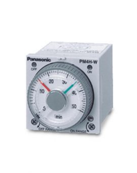
DIN 48 SIZE LCD ELECTRONIC COUNTER
UL/C-UL , CE Approved

A brand new bright 2-color backlight LCD display. The easy-to-read screen in any location makes checking and setting procedures a cinch.
Seesaw buttons make operating the unit even easier than before.
With a short body, it easily installs in even narrow control panels.
The water-proof panel keeps out water and dirt for reliable operation even in poor environments.
The two terminal types are standard options to support either front panel installation or embedded installation.
Also offers a black panel cover to meet your design considerations.
All this at an affordable price to provide you with unmatched cost performance.
Set the output 1 and output 2 with the DIP switches on the side of the counter.
The minimum input signal width and maximum counting speed for the reset are set at the same time.

Set the set value with the UP keys on the front of the counter.
|
 |
*Note:Pressing the [SET/LOCK] key switches the display between the set value 1 and 2 displays. Display either set value [1] or [2], and set the value.
Set the input mode using the key and switch in the front display section on the counter front.

Example) Input mode displayed (UP: addition mode)

Hold down the SET/LOCK key and press the UP key for the second digit. The input mode is displayed for about 2 seconds and then the display goes back to normal. (During these 2 seconds, all operations other than the display are being performed.)
Hold down the SET/LOCK key and press the UP key for the sixth digit. The keys will lock. This means that the UP and RESET keys do not respond to touch. To unlock the keys,hold down the SET/LOCK key and press the UP key for the sixth digit again.
*The input mode, maximum counting speed and minimum reset signal width cannot be preset independently for Setting 1 and Setting 2
Press the SET/LOCK key and the display changes between Setting 1 and Setting 2. (This operation does not affect overall operation.)
| Input mode | Operation | * Minimum input signal width 30 Hz: 16.7 ms; 5 kHz: 0.1 ms |
|---|---|---|
| Addition [UP] |
IN1 or IN2 works as an input block (gate) for the other input. | Example where IN1 is the counting input and IN2 is the input block (gate). Example where IN2 is the counting input and IN1 is the input block (gate).  * “A” must be more than the minimum input signal width. *n: Set value 2 |
| Subtraction [DOWN] |
||
| Directive [DIR] |
IN1 is the counting input and IN2 is the addition or subtraction directive input. IN2 adds at L level and subtracts at H level. |  * “A” must be more than the minimum input signal width. *n: Set value 2 |
| Independent [IND] |
IN1 is addition input and IN2 is subtraction input. |  * IN1 and IN2 are completely independent, so there is no restriction on signal timing. |
| Phase [PHASE] |
Addition when the IN1 phase advances beyond IN2, and subtraction when the IN2 phase advances beyond IN1. |  * “B” must be more than the minimum input signal width. |
For the set value 1, you can choose one of the following four modes.
|
For the set value 2, you can choose one of the following eight modes.
|
| Output mode | Operation | (Example when input mode is either addition or subtraction) |
|---|---|---|
| Maintain output Over count I [HOLD-B] |
Output control is maintained after count-up completion and until resetting. However, counting is possible despite completion of count-up. |  * n: Set value 1 |
| Maintain output Over count II [HOLD-C] |
Output control is maintained after count-up completion and until the next signal enters. However, counting is possible despite completion of countup. |  * n: Set value 1 |
| Maintain output Over count III [HOLD-D] |
If the count value is greater than or equal to the preset value when counting up, the control output is held. The count operation is possible anyway. |  * n: Set value 1 |
| One shot Over count [SHOT-A] |
Output control is maintained after count-up completion for a fixed time (approx. 1 sec). Counting is possible despite completion of count-up. |  * n: Set value 1 |
| Output mode | Operation | (Example when input mode is either addition or subtraction) |
|---|---|---|
| Maintain output Hold count [HOLD-A] |
Output control is maintained after count-up completion and until resetting. During that time, the count display does not change from that at count-up completion. |  * n: Set value 2 |
| Maintain output Over count I [HOLD-B] |
Output control is maintained after count-up completion and until resetting. However, counting is possible despite completion of count-up. |  * n: Set value 2 |
| Maintain output Over count II [HOLD-C] |
Output control is maintained after count-up completion and until the next signal enters. However, counting is possible despite completion of countup. |  * n: Set value 2 |
| Maintain output Over count III [HOLD-D] |
If the count value is greater than or equal to the preset value when counting up, the counter starts counting up again. The count operation is possible anyway. |  * n: Set value 2 |
| One shot Over count [SHOT-A] |
Output control is maintained after count-up completion for a fixed time (approx. 1 sec). Counting is possible despite completion of count-up. |  * n: Set value 2 |
| One shot Recount I [SHOT-B] |
Output control is maintained after count-up completion for a fixed time (approx. 1 sec). Counting is possible despite completion of count-up. However, reset occurs simultaneous with completion of count-up. While output is being maintained, restarting of the count is not possible. |  * n: Set value 2 |
| One shot Recount II [SHOT-C] |
Output control is maintained after count-up completion for a fixed time (approx. 1 sec). Counting is possible despite completion of count-up. However, reset occurs simultaneous with output OFF. |  * n: Set value 2 |
| One shot Hold count [SHOT-D] |
Output control is maintained after count-up completion for a fixed time (approx. 1 sec). During that time, the count display does not change from that at count-up completion. Reset occurs simultaneous with output OFF. |  * n: Set value 2 |

Note:When control output 1 is on, the output mode of setting 2 (SHOT-A, B, C, D) is also on and output 1 changes as shown in the above table.
| Item | Ralay output type | Transistor output type | ||||
|---|---|---|---|---|---|---|
| AC type | DC type | AC type | DC type | |||
| Rating | Rated operating voltage | 100 to 240 V AC 24 V AC | 12 to 24 V DC | 100 to 240 V AC 24 V AC | 12 to 24 V DC | |
| Rated frequency | 50/60 Hz common | – | 50/60 Hz common | – | ||
| Power consumption | Max. 10 V A | Max. 3 W | Max. 10 V A | Max. 3 W | ||
| Rated control capacity | 3 A, 250 V AC (resistive load) | 100 mA, 30 V DC | ||||
| Input mode | Addition (UP)/Subtraction (DOWN)/Direction (DIR)/Individuality (IND)/Phase (PHASE) 5 modes selectable by DIP switch | |||||
| Counting speed | 30 Hz(cps)/5 KHz(cps) (selectable by DIP switch) | |||||
| Counting input (Input 1, 2) | Min. input signal width: 16.7 ms at 30 Hz(cps)/0.1 ms at 5 KHz(cps) ON time: OFF time = 1:1 | |||||
| Reset input method | Min. input signal width: 1 ms, 20 ms (selected by DIP switch) | |||||
| Input signal | Contact or Open collector input/Input impedance: 1 kΩ or less, Input residual voltage: 2 V or less, Open impedance: 100 kΩ or less, Max. energized voltage: 40 V DC | |||||
| Output mode | Output 1. HOLD-B, C, D SHOT-A (4 modes) Output 2. HOLD-A, B, C SHOT-A, B, C, D (8 modes) (selectable by DIP switch) |
|||||
| One shot output time | Approx. 1 s | |||||
| Indication | 7-segment LCD, Counter value (backlight red LED), Setting value (backlight yellow LED) | |||||
| Digit | -99999 to 999999 (-5 digits to 6 digits) (0 to 999999 for setting) | |||||
| Memory | EEP-ROM (Overwriting times: 105ope. or more) | |||||
| Contact | Contact arrangement | 1 Form A + 1 Form A | 1 Form A + 1 Form A (Open collector) | |||
| Contact resistance (Intial value) | 100 mΩ (at 1 A 6 V DC) | – | ||||
| Contact material | Ag alloy/Au flush | – | ||||
| Life | Mechanical(contact) | Min. 2.0×10⁷ope. | – | |||
| Electrical(contact) | Min. 1.0×10⁵ope. (At rated control voltage) | Min. 1.0×10⁷ope. (At rated control voltage) | ||||
| Electrical | Allowable operating voltage range | 85 to 110 % of rated operating voltage | ||||
| Break down voltage (Initial value) |
Between live and dead metal parts: 2, 000 Vrms for 1 min (pin type) Between input and output: 2, 000 Vrms for 1 min Between open contacts: 1, 000 Vrms for 1 min |
Between live and dead metal parts: 2, 000 Vrms for 1 min Between input and output: 2, 000 V AC for 1 min |
||||
| Insulation resistance (At 500 V DC) (Initial value) | Between live and dead metal parts: Min. 100 MΩ (pin type) Between input and output: Min. 100 MΩ Between open contact: Min. 100 MΩ |
Between live and dead metal parts: Min. 100 MΩ (pin type) Between input and output: Min. 100 MΩ |
||||
| Temperature rise | Max. 65°C (under the flow of nominal operating current at nominal voltage) |
– | ||||
| Mechanical | Vibration resistance | Functional | 10 to 55 Hz (1 cycle/min), single amplitude: 0.35 mm .014 inch (10 min on 3 axes) | |||
| Destructive | 10 to 55 Hz (1 cycle/min), single amplitude: 0.75 mm .030 inch (1 h on 3 axes) | |||||
| Shock resistance | Functional | Min. 98 m/s2 321.522 ft./s2(4 times on 3 axes) | ||||
| Destructive | Min. 294 m/s2 964.567 ft./s2(5 times on 3 axes) | |||||
| Operating conditions | Ambient temperature | -10°C to 55°C/ +14 ° F to +131 ° F | ||||
| Ambient humidity | Max. 85 % RH (non-condensing) | |||||
| Air pressure | 860 to 1, 060 h Pa | |||||
| Ripple rate | – | 20 % or less | – | 20 % or less | ||
| Connection | 11-pin/screw terminal | |||||
| Protective construction | IP66 (front panel with a rubber gasket) | |||||