UL/C-UL , CE Approved
The operation time range covers from 0.01 sec. to 999 hours.
The individual setting can be performed on each of 1 and 2 timers.
99.99s 99min59s99h59min
999.9s 999min999.9h
9999s9999h
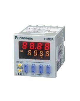
A brand new bright 2-color back light LCD display. The easy-to-read screen in any location makes checking and setting procedures a cinch.
Seesaw buttons make operating the unit even easier than before.
With a short body, it is easy to install in even narrow control panels.
The water-proof panel keeps out water and dirt for reliable operation even in poor environments.
The two terminal types are standard options to support either front panel installation or embedded installation.
Also offers a black panel cover to meet your design considerations.
All this at an affordable price to provide you with unmatched cost performance.
Set the time range with the DIP switches on the side of the LT4H-W timer.
Set the operation mode with the keys on the front of the LT4H-W timer.
|
 |
1.When the UP or DOWN key at the first digit is pressed with the SET/LOCK switch pressed, the mode is changed over to the setting mode.
2.Now release the SET/LOCK switch.
3.The operation mode in the setting mode is changed over sequentially in the left or right direction by pressing the UP or DOWN key at the first digit, respectively.
4.The operational mode displayed at present is set by pressing the RESET switch, and the display returns to the normal condition.
1.Pressing the SET/LOCK key switches the set value display between T1 and T2. Display the timer (T1 or T2) which is to be set (or changed).
2.After displaying the timer (T1 or T2) which is to be set, press the UP or DOWN key to change the time.
When the UP or DOWN key at the second digit is pressed with the SET/LOCK switch pressed, the operational mode can be checked.
The display returns to the normal condition after indicating the operational mode for about two seconds. (While the display indicates the operational mode for about two seconds, the other indicators continue to operate normally.)
When the UP or DOWN key at the fourth digit is pressed with the SET/LOCK switch pressed, all keys on the unit are locked.
The timer does not accept any of UP, DOWN and RESET keys.
To release the lock setting, press the UP or DOWN key at the fourth digit again with the set/lock switch pressed.
*Operational mode, adding and subtracting and minimum input signal range cannot be set at T1 and T2, respectively.
The T1/T2 setting display is changed over by pressing the SET/LOCK switch. (This operation gives no effect on the other operations. The set time and elapsed time (residual time) at T1 are linked with those at T2.)
| A Delayed one shot |
[PULSE] [A] OFF-start/1 operation t1 < T1, t2 < T2 ・Elapsed value cleared when power is turned on. ・Time limit start initiated when start input goes on; start input ignored if time limit interval is in progress. ・Elapsed value cleared when one operation has been completed. |
|---|---|
| B OFF-start flicker |
[PULSE] [B] OFF-start/repeating operation t1 < T1, t2 < T2 ・Elapsed value cleared when power is turned on. ・Time limit start initiated when start input goes on; start input ignored if time limit interval. |
| C ON-start flicker |
[PULSE] [C] ON-start/repeating operation t1 < T1, t2 < T2 ・Elapsed value cleared when power is turned on. ・Time limit start initiated when start input goes on; start input ignored if time limit interval is in progress. |
| Remarks and notes |
・The pulse input mode starts the operation by starting the start input. ・When using the unit by starting it with the power on, shortcircuit the start terminal (8-pin: Q to R, 11-pin: E to Y and screw terminal: to ). |
| ・Each signal input such as start, reset, stop and lock inputs is applied by short-circuiting its input terminal and common terminal (8-pin type: terminal Q, 11-pin type: terminal E and screw terminal: terminal ) respectively. ・The 8-pin type does not have a stop input or lock input. |
| A Delayed one shot |
[INTEGRATION] [A] OFF-start/1 operation t1 < T1, t2 < T2 ・Elapsed value not cleared when power is turned on (power failure backup function). ・When power is turned back on, same status is maintained for output as that previous to power going off. ・Elapsed value cleared when one operation has been completed. |
|---|---|
| B OFF-start flicker |
[INTEGRATION] [B] OFF-start/repeating operation t1 < T1, t2 < T2 ・Elapsed value not cleared when power is turned on (power failure backup function). ・When power is turned back on, same status is maintained for output as that previous |
| C ON-start flicker |
[INTEGRATION] [C] ON-start/repeating operation t1 < T1, t2 < T2 ・Elapsed value not cleared when power is turned on (power failure backup function). ・When power is turned back on, same status is maintained for output as that previous to power going off. |
| Remarks and notes |
・The integrating input mode is operated by the integrated time of the start input. In other word, the timer operates only when the start input is performed. ・When the elapsed value is cleared by the reset input, the output is reset. ・When using the unit by starting it with the power on, shortcircuit the start terminal (8-pin: Q to R, 11-pin: E to Y and screw terminal: to ). |
| ・Each signal input such as start, reset, stop and lock inputs is applied by short-circuiting its input terminal and common terminal (8-pin type: terminal Q, 11-pin type: terminal E and screw terminal: terminal ) respectively. ・The 8-pin type does not have a stop input or lock input. |
| Item | Ralay output type | Transistor output type | ||||
|---|---|---|---|---|---|---|
| AC type | DC type | AC type | DC type | |||
| Rating | Operating voltage | 100 to 240 V AC, 24 V AC | 12 to 24 V DC, 24 V AC | 100 to 240V AC, 24 V AC | 12 to 24 V DC, 24 V AC | |
| Frequency | 50/60 Hz common | – | 50/60 Hz common | – | ||
| Power consumption | Max. 10 V A | Max. 3 W | Max. 10 V A | Max. 3 W | ||
| Control capacity (resistive) | 5 A, 250 V AC (Resistive load) | 100 mA, 30 V DC | ||||
| Time range | 99.99 s, 999.9 s, 9999 s, 99 min 59 s, 999.9 min. 99 h 59 min, 999.9 h (selected by DIP switch) | |||||
| Time counting direction | Addition (UP)/Subtraction (DOWN) (2 directions selectable by DIP switch) | |||||
| Operation mode | Pulse input: Delayed one shot, OFF-start flicker or ON-start flicker Integrating input: Delayed one shot, OFF-start flicker or ON-start flicker | |||||
| Signal/Reset/Stop input | Min. input signal width: 1 ms, 20 ms (2 directions by selected by DIP switch) | |||||
| Lock input | Min. input signal width: 20 ms | |||||
| Input signal | Open collector input Input impedance: Max. 1 kohm; Residual voltage: Max. 2V Open impedance: 100 kohm or less, Max. energized voltage: 40 V DC | |||||
| Indication | 7-segment LCD, Elapsed value (backlight red LED), Setting value (backlight yellow LED) | |||||
| Power failure memory method | EEP-ROM (Min. 105overwriting) | |||||
| Time accuracy (max.) | Operating time fluctuation | ±(0.005%+50 ms) in case of power on start ±(0.005%+20 ms) in case of reset or input signal start [Operating voltage: 85 to 110% Temperature: -10 to +55°C +14 to +131 ° F Min. input signal width: 1ms] | ||||
| Temperature error | ||||||
| Voltage error | ||||||
| Setting error | ||||||
| Contact | Contact arrangement | Timed-out 1 Form C | Timed-out 1 Form A (Open collector) | |||
| Initial contact resistance | 100 mohm (at 1 A 6 V DC) | – | ||||
| Contact material | Ag alloy/Au flash | – | ||||
| Life | Mechanical | 2.0 × 10⁷ope. (Except for switch operation parts) | – | |||
| Electrical | 1.0 × 10⁵ope. (At rated control voltage) | 1.0 × 10⁷ope. (At rated control voltage) | ||||
| Electrical | Operating voltage range | 85 to 110% of rated operating voltage | ||||
| Initial breakdown voltage | 2, 000 Vrms for 1 min: Between live and dead metal parts (11-pin) 2, 000 Vrms for 1 min: Between input and output 1, 000 Vrms for 1 min: Between contacts | 2, 000 Vrms for 1 min: Between live and dead metal parts (Pin type) 2, 000 Vrms for 1 min: Between input and output | ||||
| Initial insulation resistance (At 500 V DC) | Min. 100 Mohm: Between live and dead metal parts Between input and output Between contacts | Min. 100 Mohm: Between live and dead metal parts Between input and output | ||||
| Operating voltage reset time | Max. 0.5 s | |||||
| Temperature rise | Max 65°C (under the flow of nominal operating current at nominal voltage) | |||||
| Mechanical | Vibration resistance | Functional | 10 to 55 Hz: 1 cycle/ min single amplitude of 0.35 mm .014 inch (10 min on 3 axes) | |||
| Destructive | 10 to 55 Hz: 1 cycle/ min single amplitude of 0.75 mm .030 inch (1 h on 3 axes) | |||||
| Shock resistance | Functional | Min. 98 m 321.522 ft./s2(4 times on 3 axes) | ||||
| Destructive | Min. 294 m 964.567 ft./s2(5 times on 3 axes) | |||||
| Operating conditions | Ambient temperature | -10°C to 55°C + 14 ° F to + 131 ° F | ||||
| Ambient humidity | Max. 85% RH | |||||
| Air pressure | 860 to 1, 060 h Pa | |||||
| Ripple rate | – | 20% or less | – | 20% or less | ||
| Connection | 8-pin/11-pin/screw terminal | |||||
| Protective construction | IP66 (front panel with rubber gasket) | |||||
Ultra-compact body equipped with a 3.5 inch QVGA display.
UL/C-UL , CE Approved CE : EMC Directive UL : Approved Listing